Wheel Alignment AXIS500
AXIS500 Manual Instructions
6 Rear Wheel Alignment
The front wheels are aligned.
Retro-fit the measuring head on the measuring
stand (on the instrument cabinet) with the long
magnetic feet (315 mm).
Remark: The rims and the magnets have to
be clean of excess paint, mud and corrosion.
6.1 Camber Measurement of the Rear Wheels
For mounting and operation of the electronic
inclinometer, see point 5.6 on page 24.
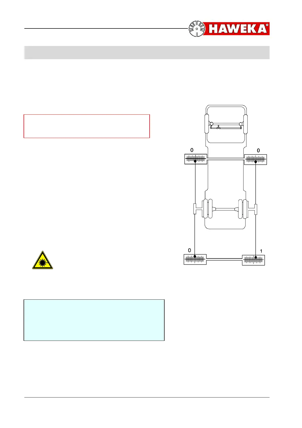
6.2 Total Toe / Rear Axle
Set up the toe-scales exactly as described in
section 5.3 on page 21 . both scales are set to
0 (zero) in front of rear axle.
Pay attention to laser beam
output opening before switch
on of laser measuring heads!
Example, illustration 23,
Right laser beam behind right rear axle points at the
first long scale line outward; indicating that the rear
axle has a toe-in of 1 mm