Wheel Alignment AXIS500
AXIS500 Manual Instructions
Trucks with Independent Suspensions
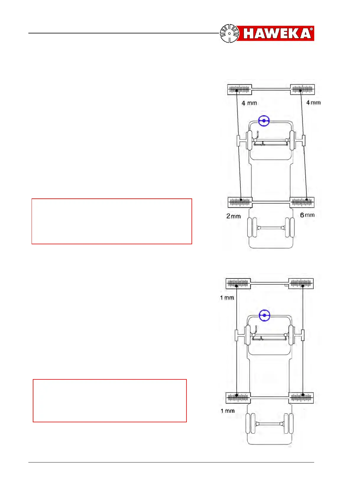
E.g. the following values are indicated:
(Illustration 33).
At the rear left-hand side 2 scale lines inward
from zero, at the front left-hand side 4 scale
lines outward from zero. This means that the
left wheel has a toe-out of 6 mm.
At the rear right-hand side 6 scale lines
outward from zero, at the front right-hand side
4 scale lines inward from zero. This means that
the right wheel has a toe-in of 10 mm.
Now lock the steering wheel.
Note:
Make sure that the “straight ahead position“
of the steering wheel is not changed when
adjusting the rod.
In order to set the left wheel at a toe of zero
the toe rod is turned until the laser points both
on the front and rear left-hand side indicate
identical values. For the present example, this
means one scale line outward from zero on the
front left-hand scale and one scale line outward
from zero on the rear left-hand scale
(illustration 34). In order to set the right wheel
at a toe of zero, the right toe rod has to be
turned until the laser points both on the front
and rear right-hand side also indicate identical
values.
Note:
After finishing procedure, the „straight
ahead position“ must automatically be
recreated.
 Loading...