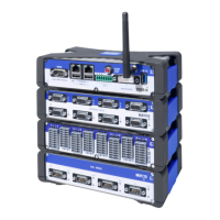
In Slave mode:
l the top connector is configured as slave input, all other connectors are
unused
l all received signals are transferred to a bus for internal distribution
l internal slave trigger signals are transferred to the outside
In Stand-alone mode:
l
Stand-alone mode is OFF: the Master/Slave card does not communicate
with other Master/Slave cards.
Fiber optic cable
The
Master/Slave card has optical I/O (IN/OUT) that connects to other Master/
Slave cards.
The fiber optic cable:
l allows up to a
500 m cable between the master and each slave (for more
information, please refer to "Calculating maximum fiber cable length" on
page 945)
l distributes the sampling clock, absolute time info, trigger and start/stop
signals between mainframes, creating a real high channel synchronized
system out of the nine mainframes
l enables a timing accuracy between the mainframes less than 100 ns
K.5.1 Master/Slave card operations
The Master/Slave card is easily inserted into the GEN series mainframe and is
automatically recognized by the Perception software. A Master/Slave card can
be used as a master or slave. One card is required in the master mainframe
and one card is required per slave mainframe. Each card has eight LC
®
connectors for the fiber optic cable.
GEN3i
1002 I3763-3.1 en HBM: public


 To Next Page