15.3 Probe bandwidth calibration
A probe makes a physical and electrical connection between a test point or
signal
source and the instrument. Depending on the measurement needs, this
connection can be made with something as simple as a length of wire or with
something as sophisticated as an active differential probe.
For the purpose of this document, we only describe attenuating probes within
two categories: 1X Probes and 10X Probes.
15.3.1 1X Probes
1X probes, also known as 1:1 (one-to-one) probes, simply connect the input of
the instrument to the circuit being measured. They are designed for minimum
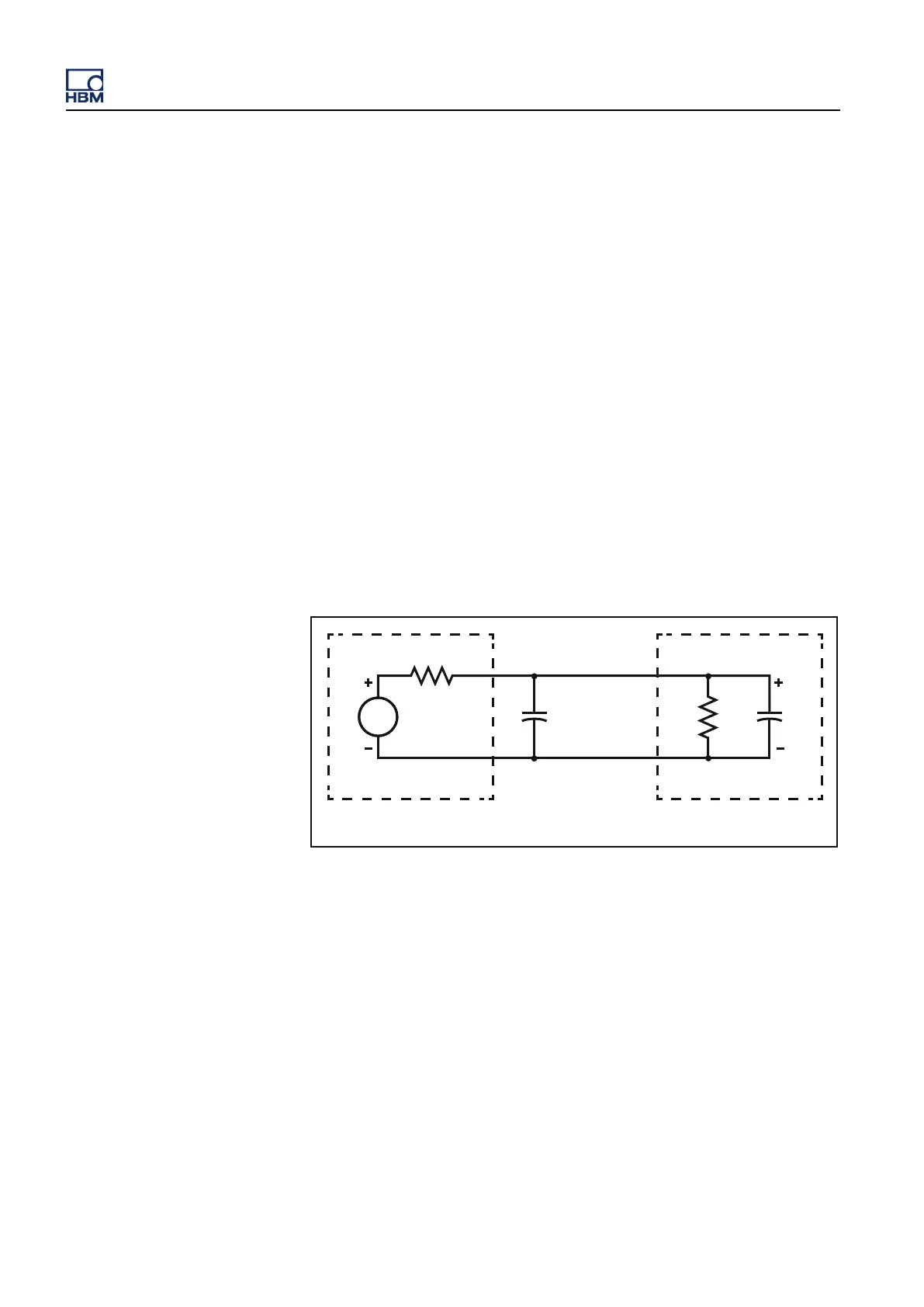
loss and easy connection. Figure 15.12 shows the circuit diagram for an
instrument input connected to a circuit under test. The circuit under test is
modeled as a voltage source with a series resistor. The 1X probe (or cable)
introduces a significant amount of capacitance that appears in parallel with the
input of the instrument. A 1X probe may have around 40 to 60 pF of
capacitance.
R
S
R
IN
V
S
V
IN
C
probe
C
IN
Circuit under test Input
Figure 15.12: Input connection using a 1X probe
The
impedance of the circuit and the input impedance of the instrument produce
a lowpass filter. For very low frequencies, the capacitor acts as an open circuit
and has little or no effect on the measurement. For high frequencies, the
capacitor's impedance becomes significant and reduces the voltage detected
by the instrument. Figure 15.13 shows this effect in the frequency domain. If
the input is a sine wave, the amplitude tends to decrease with increasing
frequency and the phase is shifted.
GEN3i
360 I3763-3.1 en HBM: public
 Loading...