Bridge balance
The bridge circuit is only in balance (has no output when the bridge voltage is
applied) when R1 / R2 = R4 / R3. Taking the various resistance tolerances on
the strain gauge(s), resistors and lead wires into account, an initial unbalance
is
invariably present. Adjusting the initial balance so that there is zero output at
zero strain is achieved by bridge balancing.
While resistive-balance circuits are widely used in strain gauge instrumentation,
GN410 and GN411 use an alternative electronic method of balancing the output
to zero, involving measuring the output of the bridge and injecting an equal and
opposite voltage. This method permits rapid automatic balancing in multi-
channel systems and eliminates the bridge loading errors that can occur in the
resistive system when making measurements with precision strain gauge
transducers.
HINT/TIP
When doing a bridge balance, the GN410 and GN411 acquisition card
measures the input value at the connector of the acquisition card. This means
it cannot “see” if a bridge is actually connected or not. No voltage present can
mean that the bridge is balanced or that no bridge is connected.
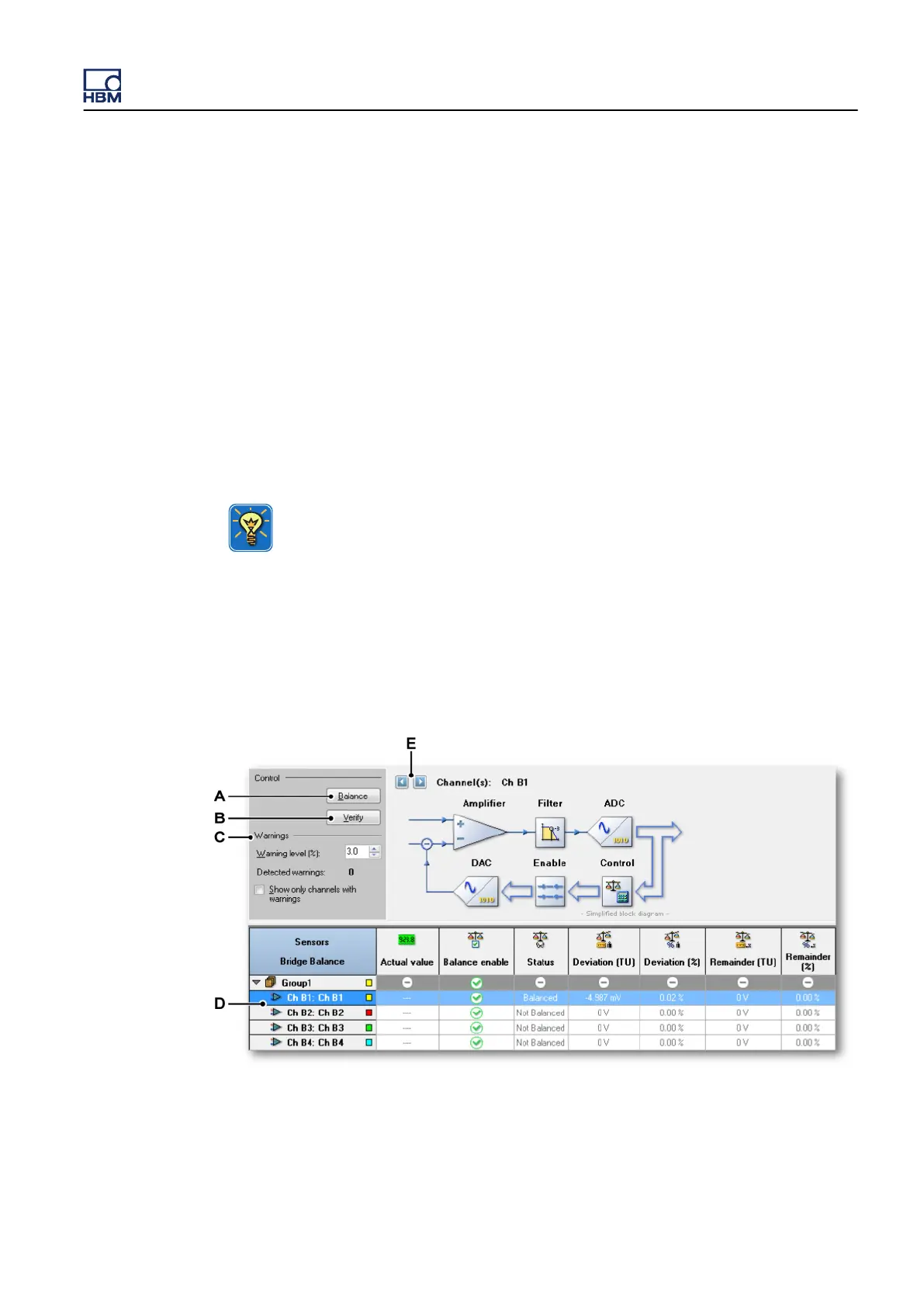
Bridge balancing in Perception is done with the Bridge Balance dialog.
Figure 12.44: Bridge Balance dialog
A Balance command
B Verify command
GEN3i
I3763-3.1 en HBM: public 271