CAUTION
The
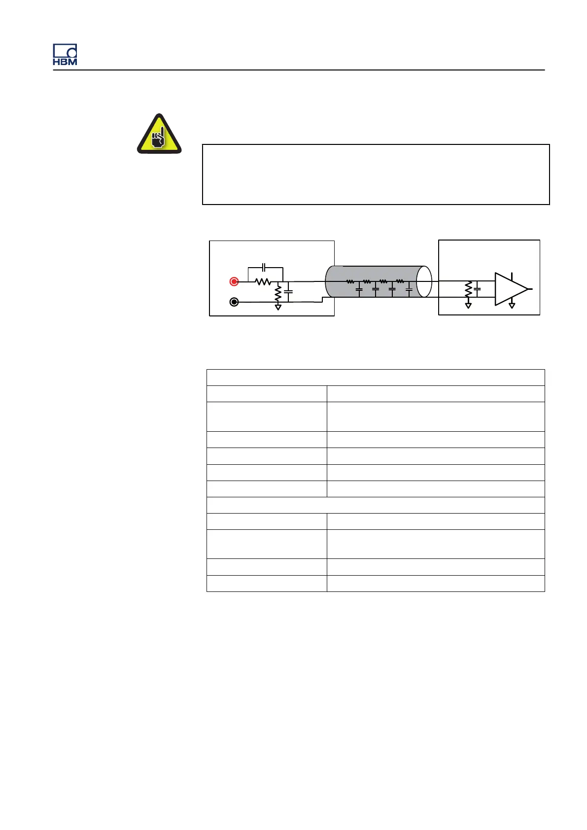
coaxial cable attached to the 1kv DC probe adds a capacitive load to
the output of the probe. Every cm length added or removed changes the
capacitive load. By design, the cable length of the 1kV DC probe is fixed
and cannot be changed.
Coax cable
C3
a
C3
b
C3
c
C3
d
≤ 0.01Ω
≤ 0.01Ω
- - - - - -
900 kΩ
111 kΩ
C1
C2
1kV DC-Probe (1-G041-2)
+
-
1 MΩ
Schematic input
diagram GN813/814
C4
Figure K.2: 1kV DC probe cable capacitance
Specifications
Number of channels 1 per probe, 16 per probe rack
Input type
Isolated unbalanced differential (isolated single-
ended)
Input connectors 2; 4 mm safety banana plugs (red and black)
Input impedance
1 MΩ ± 1%
; when using a 1 MΩ output load
Divider ratio 1:10
Inaccuracy 0.1%
Maximum input voltage
Positive input (red) 1000 V DC
Negative input (black) 250 V DC; As specified by GN813 and GN814
cards
Bandwidth
250 kHz ± 10% (-3 dB)
Coax cable length Fixed; Several variances as delivered
GEN3i
I3763-3.1 en HBM: public 993
 Loading...