B-3
Structure of the PC measurement electronics with Spider8 Ý Connection facilities
Spider8
1 Connection facilities
Channels
Ground connection
13
SPIDER8
carrier-frequency 4.8kHz
For
Spider8-30:
SPIDER8-30
TF
600Hz
Spider8-01:
DC/4.8 kHz
DC/600 Hz
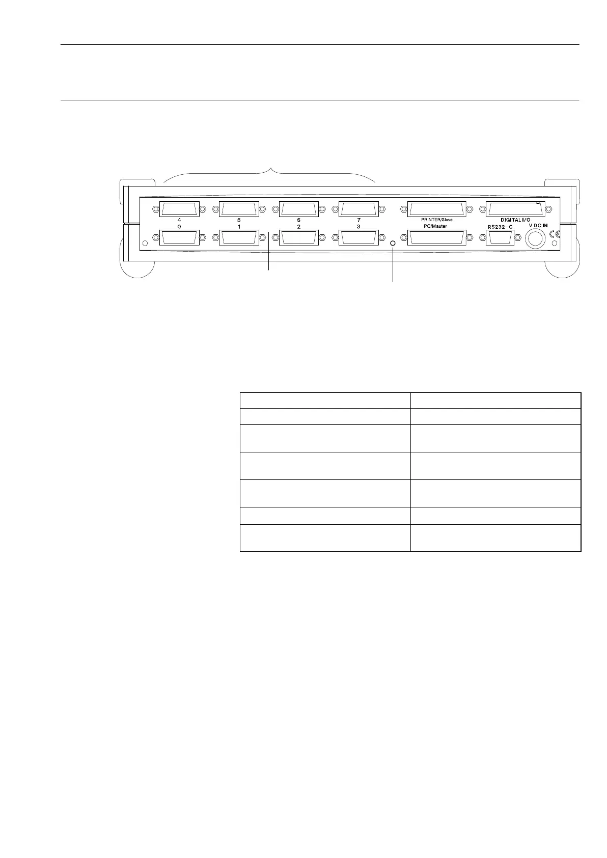
Fig. B 1: Back side of the device
The device has the following connection facilities:
Connection facility Meaning
Channel 0 to 7 Transducer port
PRINTER/Slave, 25-pin socket
(IEEE1284)
Port for printer, port for additional
Spider8
PC/Master, 25-pin socket
(IEEE1284)
Port for PC and additional
Spider8
DIGITAL I/O, 25-pin socket
(IEEE1284)
8 digital inputs and
8 digital inputs/outputs
RS-232-C, 9-pin socket
Port for PC
13V DC IN, 4-pin socket Connection for external power
supply (power pack, battery)