2514
1
13
B-11
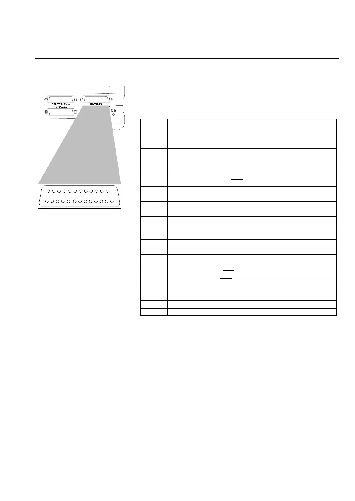
Structure of the PC measurement electronics for Spider8 Ý I / O socket
Spider8
3 I / O socket
Eight digital inputs and eight I/Os (8-bit input / 8-bit output) are
available on this socket besides control signals and status
messages. The contacts are not electrically isolated.
Pin assignment for the I/O socket:
Pin Assignment
1 +5V/R
i
= 1kΩ
2 Ground
3 Input 14
4 Input 12
5 Input 10
6 Input 8
7 Ground
8 MSR (Measure)*
9 Ground
10 Input / Output 6
11 Input / Output 4
12 Input / Output 2
13 Input / Output 0
14
Start (external trigger for measurement sequence)
15 Input 15
16 Input 13
17 Input 11
18 Input 9
19 COMMON (common protective diode connection for external relay)
20
ERR (Command Error)*
21
RDY (Waiting for Trigger)*
22 Input / Output 7
23 Input / Output 5
24 Input / Output 3
25 Input / Output 1
* Description with an over-rule means : zero value indicates active status.