B-5
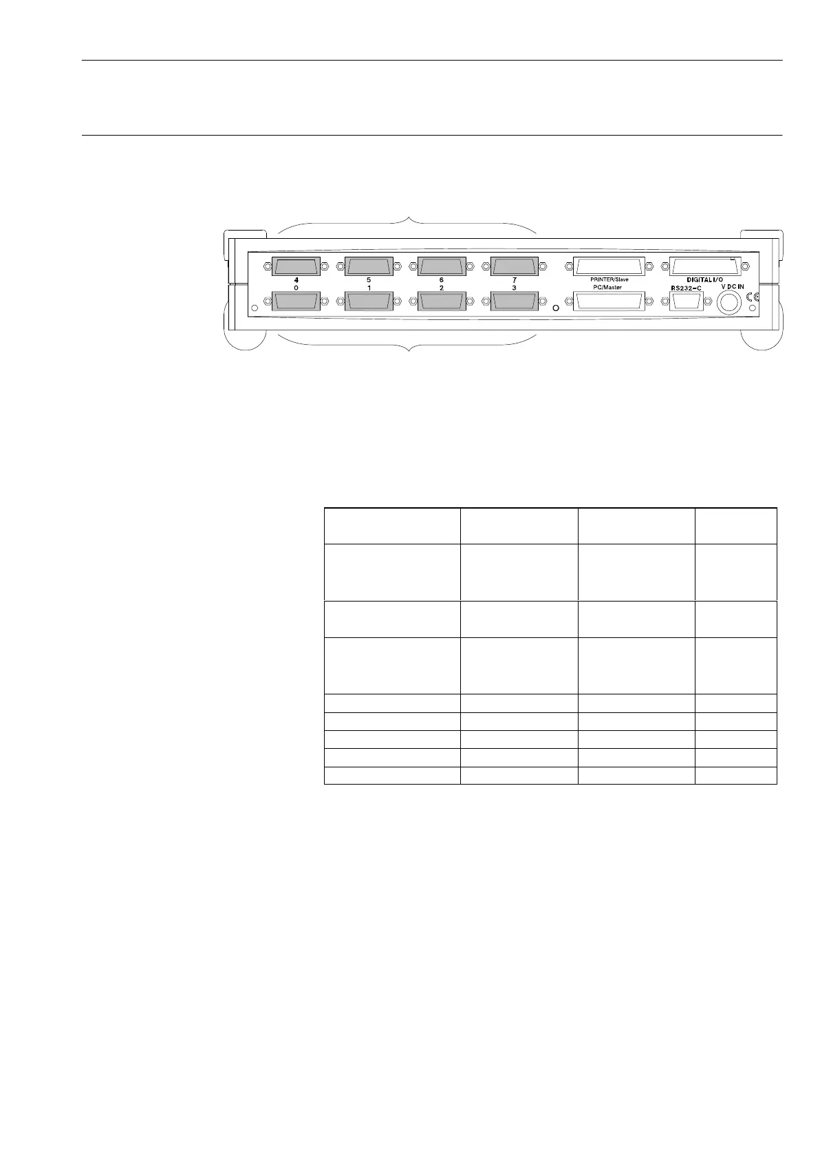
Structure of the PC measurement electronics with Spider8 Ý Connection facilities
Spider8
1.2 Modules (carrier-frequency/DC)
Channel 0 to 3: permanent carrier-frequency amplifier modules
Channels 4 to 7: optional carrier
-frequency or DC amplifier modules (SR55, SR30, SR01)
13
SPIDER8
carrier-freq
uency
4.8kHz
On the basic version of the device, channels 0 to 3 are fitted with
4.8kHz carrier-frequency amplifiers (600Hz for Spider8-30)and
channels 4 to 7 are closed off with blank plates.
With Spider8, channels 4 to 7 can either be fitted with 4.8kHz
carrier-frequency amplifiers (SR55) or DC amplifiers (SR01); with
Spider8-30 the options are 600Hz amplifiers (SR30) or DC
amplifiers (SR01). The appropriate transducers are connected to
these modules (see also Chapter D-3).
Transducer 4.8kHz CF module 600Hz CF module DC module
Channel Channel Channel
S/G full bridge
S/G half bridge
S/G quarter bridge
0...7
0...7
-
0...7
0...7
0...7
-
-
Inductive full bridge
Inductive half bridge
0...7
0...7
-
-
-
-
DC 10V
DC 1V
100mV DC
0..7
-
-
0...7
-
-
0...7
0...7
0...7
DC current - - 0...7
Frequency (counter) 0, 1 - -
Resistance - - 0...7
Potentiometer 0...7 0...7 -
Thermocouple - - 0...7
Chapter C ”Commissioning” tells you how you can later fit channels
4 to 7 with modules.