9
15
1
8
15-pin socket
INA
Ground
INB (High)
15-pin socket
9
10
4
3
Clear (Low
active)
Shield
Metering pulses 1
Direction
or metering
pulses 2 (90
o
offset to 1)
Clear
+5V
10kΩ
+5V
10kΩ
+5V 10kΩ
2
+10V
D-26
Connecting Ý Connecting transducers
Spider8
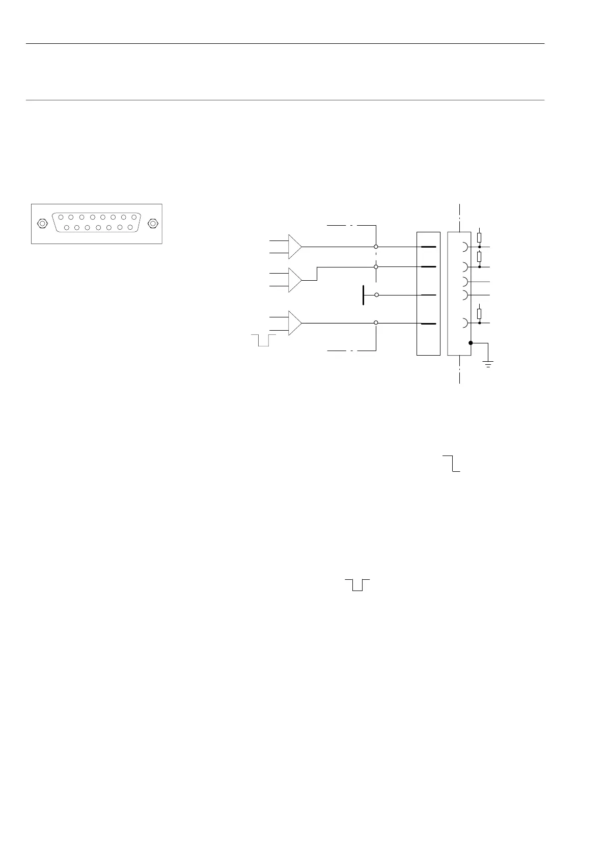
3.8 Frequency measurement / pulse counters
Connecting to carrier-frequency module SR55,
channels 0 and 1
Incremental rotary encorder with TTL/HCMOS output
Pin 2 = 10V, max. 100mA (total of all channels)
Pin10= Directional signal for metering pulse 1
forwards
backwards
or metering pulse 2 input, 90
o
offset to metering pulse 1
Pin 9 and Pin 10: max. "20V,
Switching threshold High u2.5V, Low t2V
Pin 3: Clear = counter reset
u850µs