9
15
1
8
15-pin socket
D-15
Connecting Ý Connecting transducers
Spider8
Connection to Spider8-30
Connection to carrier-frequency module SR30
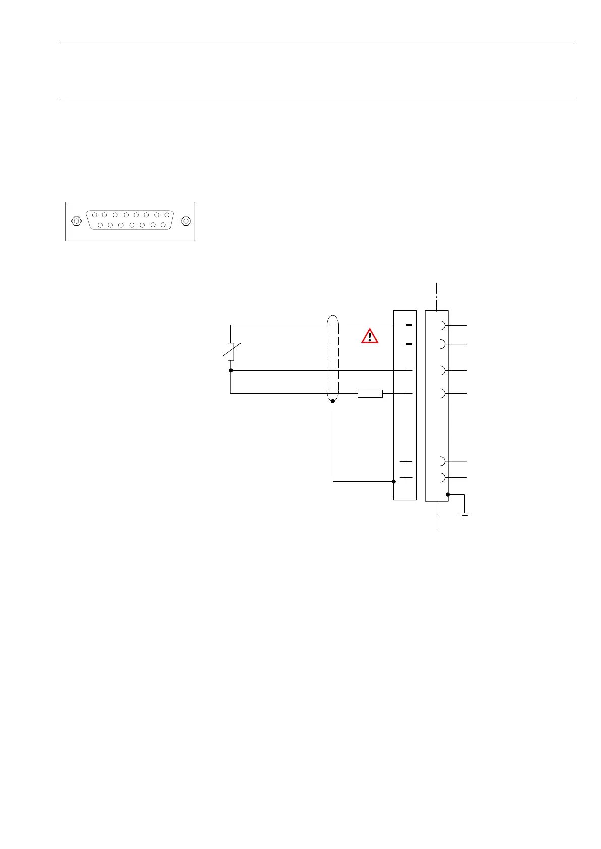
3.1.5 Special S/G using three-wire connection
(Increasing the internal compensating resistance)
8
5
12
Measurement signal
Bridge excitation
voltage
Sensor circuit (open)
Sensor circuit
Bridge excitation
voltage
1
2
3
3’
2’
13
6
bk
wh
bu
15-pin socket
Compensating resistor
(internal):
Pin3: 120Ω
Pin10: 350Ω
Pin9: 700Ω
120Ω to
1000Ω
R
user
R
user
=R
S/G
-R
internal
R
S/G
3
or
10
or
9
Link open
Mode for this connection: quarter bridge.
R
user
, mounted externally in the connector, is used to increase the
internal compensating resistance to R
S/G
.