9
15
1
8
15-pin socket
D-16
Connecting Ý Connecting transducers
Spider8
Connection to Spider8-30
Connection to carrier-frequency module SR30
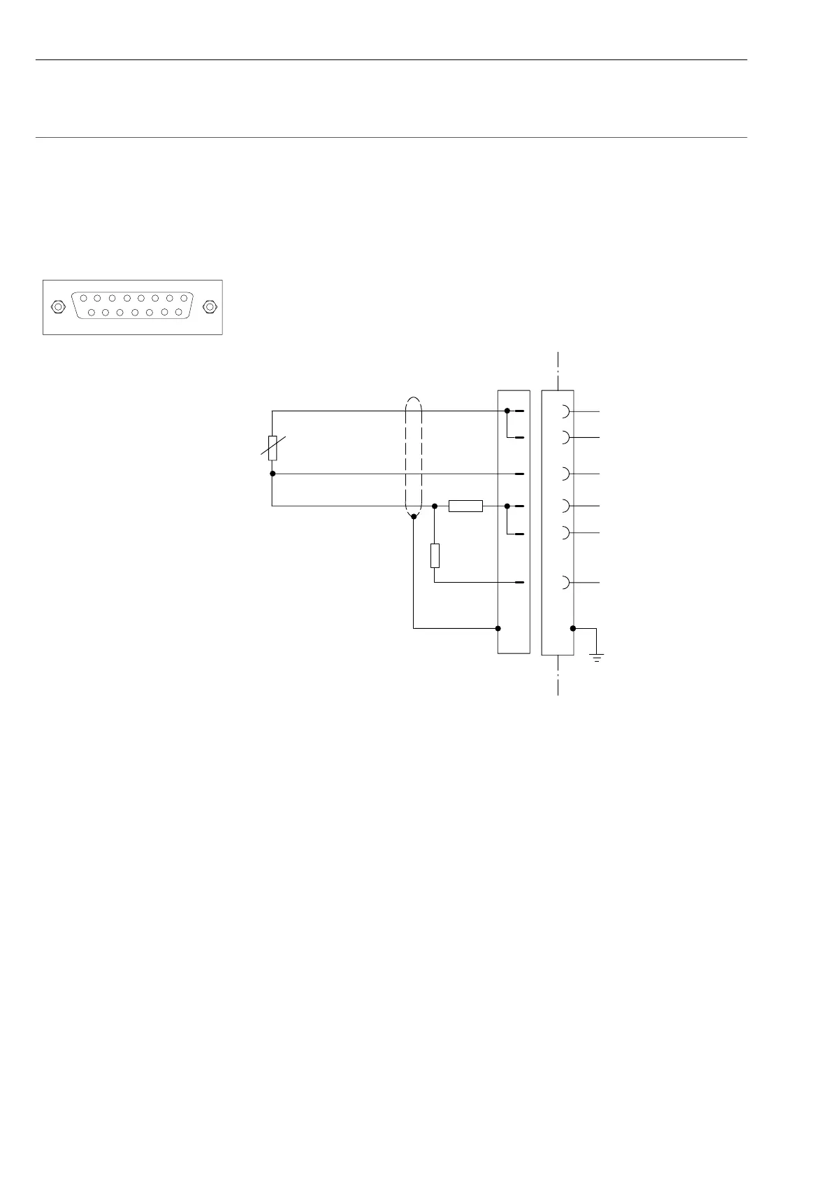
3.1.6 Special S/G using three-wire connection
(External compensating and shunt resistor)
8
5
12
Measurement signal
Bridge excitation
voltage
Sensor circuit (open)
Sensor circuit
Bridge excitation
voltage
1
2
3
3’
2’
13
11
bk
wh
bu
15-pin socket
6
120Ω to
1000Ω
R
user
R
user
=R
S/G
R
S/G
Shunt connection
R
shunt
Mode for this connection: half bridge.
The half bridge supplement is made complete with external
compensating resistors.
The shunt calibration enables you to measure the sensitivity loss
through cable resistances.