D-5
Connecting Ý Connecting transducers
Spider8
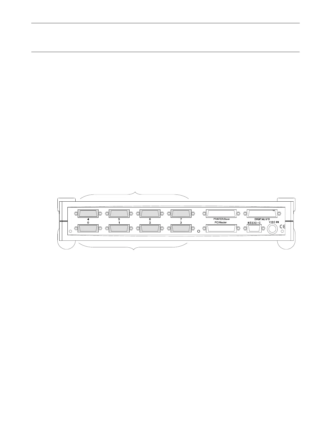
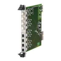
3 Connecting transducers
Transducers are connected to channels 0 to 7 (carrier-frequency
and DC modules).
Channels 0 to 3 are permanently assigned to carrier-frequency
modules. Channels 0 and 1 also provide a frequency measuring
facility
1)
.
Channels 4 to 7 can optionally be assigned carrier-frequency or DC
modules.
In the case of DC modules, all connections are
potential-segregated.
Channels not used must be covered by blank plates.
Channels 0 to 3: internal carrier-frequency modules
Channels 4 to 7: optional carrier-frequency or DC amplifier modules (SR55
1)
, SR01, SR30
2)
)
13
1)
only for Spider8
2)
only for Spider8-30
see also table on page A-9