HDL KNX / EIB Switch Actuators
_____________________________________________________________________________________
Guangzhou Hedong Electronic Co.,Ltd (HDL)
www.hdlchina.com 35/58
3.5.7 Channel function “logic”
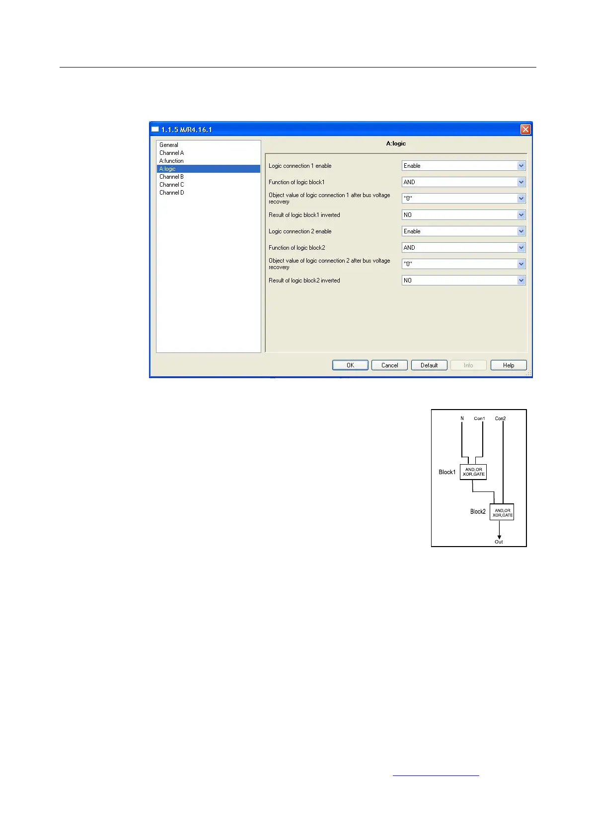
Fig13: Logic function windows
The logic functions block show at right side
graphic , it include two logic block in side , logic
block 1 has two input which are “N” and connect 1
(“Con1”), the output of logic block 1 is connected
to input of logic block 2 . logic block 2 has two
input which are connect2(“Con2”) and output of
logic block1 , the output of logic block2 is “Out”
“Logic connection 1” and “Logic connect ion 2”.
Both of logic block 1 and 2 allow select “AND”,
“OR”, “XOR”, “GATE” logic by user
--- logic connection1 enable
Enable this parameter, the logic connecton1 in
active state. The logic block 1 will no function by disable
connect1(“Con1”) , means the “N” connect to logic block 2 directly
Options: Disable
Enable
Disable: disable logic connection1
Enable: enable logic connection1
--- Function of logic block1
 Loading...