Chapter 3. Wiring and Signals
3-13
[Types and functions of CN1 input contact signal]
Pin Name
(CN1-)
Speed
control
signal
function
Position
control
signal
function
Torque
control
signal
function
Contact status
SVONEN (18)
Servo drive
ENABLE
Servo drive
ENABLE
Servo drive
ENABLE
ON = Servo drive ENABLE
SPD1/GEAR1 (43) rpm select 1
Electronic
gear select 1
Speed limit
select 1
SPD2/GEAR2 (17) rpm select 2
Electronic
gear select 2
Speed limit
select 2
Refer to:
7.7 Speed command input
8.7 Position command input
9.6 Speed limit method
SPD3/TYPE (42) rpm select 3
Refer to:
7.7 speed command input,
Chapters 10, 11 and 12
DIR (16)
Rotation
direction
select
ON = opposite direction of
speed command
OFF = same direction of speed
Command
CCWLIM (15) CCW limit CCW limit CCW limit Off = CCW limit
CWLIM (40) CW limit CW limit CW limit Off = CW limit
TLIM (14)
Analog
torque limit
Analog
torque limit
Analog
torque limit
On = Analog torque limit
Off = Digital torque limit
ALMRST/CLR (38)
ALARM
RESET
Alarm
reset/Cumul
ative pulse
clear
Alarm reset
ON = Alarm reset
ON = Cumulative pulse clear
ESTOP (39)
Emergency
stop
Emergency
stop
Emergency
stop
Contact form can be selected at
parameter [P2-30]
PI/P (41) PI/P select PI/P select
ON = Controls speed controller
P
Off = Controls speed controller
PI
STOP/START (13) Stop/Start
Can be selected at parameter
[P2-29]
Where ON: Applicable contact connected to "GND 24"
OFF: Applicable contact connected to "+24V", or applicable contact not connected.
For more details, refer to Chapter 7 through Chapter 12.
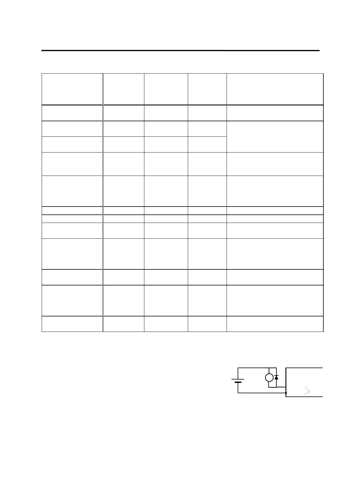
3.4.5 Output contact signal
The output contact signal functions are shown on the following
table. The output contact internally uses transistor switch. Take
precaution because overvoltage or overcurrent may cause
damage to the system. (Power supply: DC +24 [V] ±10%).
Brake signal is used to drive the brake installed inside the
motor. The sequence must be configured so when this output is turned on, power is supplied to
the brake and the break is released . Other signals are the outputs which indicate the status of the
drive system and the motor. Each function is shown on the following table.
Driver
Output contactor wiring(example)
GND24
BRAKE
24[V]
M1