Chapter 3. Wiring and Signals
3-21
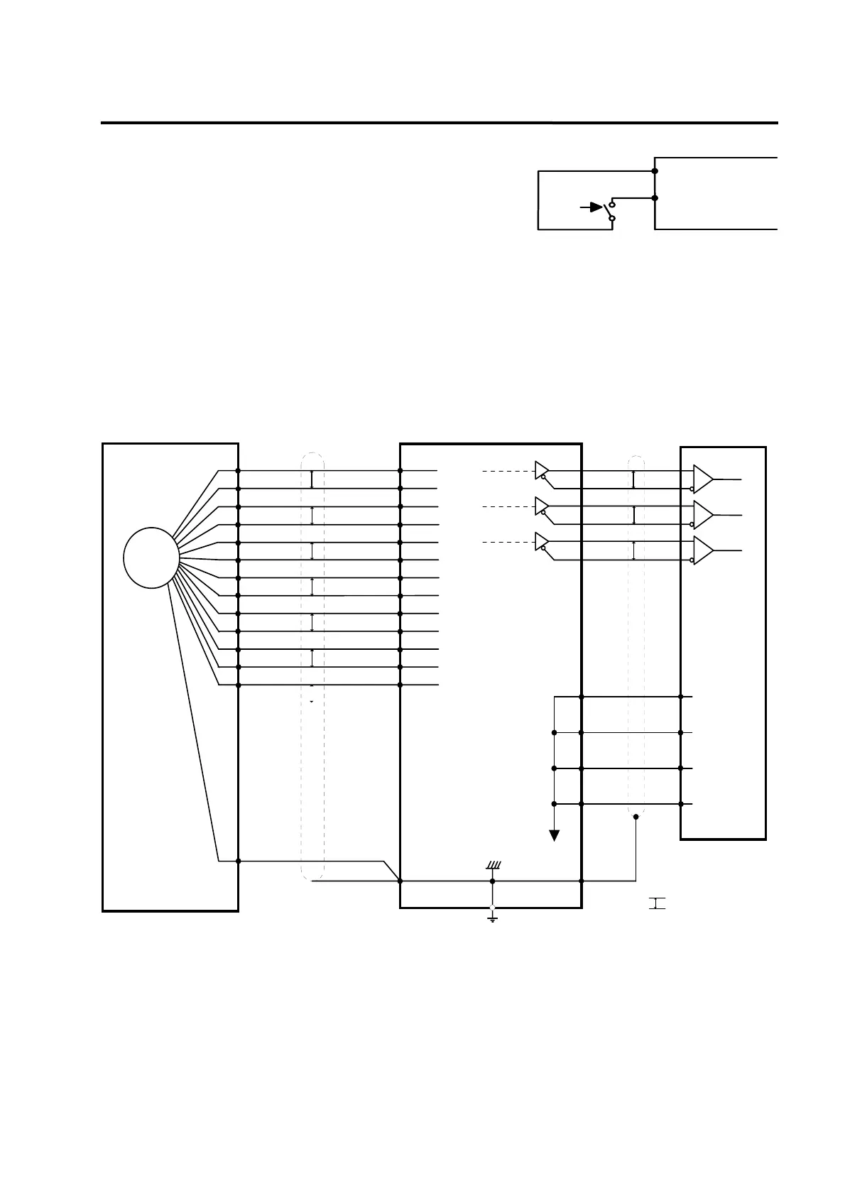
Press the encoder Reset switch connected between the
encoder reset terminal ERST (CN2-20) and the Vcc terminal
(CN2-19) for longer than 4 seconds to set the zero point of
the absolute value encoder itself or in case of alarm.
[Example of wiring between motor side (
□60, 80 series) and FDA 5000 CN2 when absolute
value encoder is used]
2-12
EN
1
2
3
4
5
6
11
12
9
10
13
14
7
8
P
P
P
P
P
P
Motor side(□60,80)
Absolute Encoder
2-18
2-15
2-16
2-13
2-14
2-11
2-1
2-2
2-7
2-8
2-20
2-19
2-9
PA
/PA
PB
/PB
PZ
/PZ
RX
/RX
BAT+
BAT-
ERST
Vcc(5V)
GND(0V)
CN2 CN1
Controller
1-7
1-32
1-6
1-31
1-5
1-30
AC SERVO DRIVER (FDA 5000A)
1-1
1-8
1-33
1-34
0V
PA0
/PA0
PB0
/PB0
PZ0
/PZ0
P
P
P
Applicable
LINE RECEIVER
T.I SN75175
Output LINE DRIVER
T.I SN75174
[*1]
[*1]
[*2]
1-50
[*1] indicates twist pair wire. P
[*2] T.I:TEXAS INSTRUMENT
[ CN2 Wiring diagram ]
Driver
[Wiring of encoder reset switch]
+5V(Vcc)
ERST
ON
CN2-19
CN2-20