Chapter 6. Parameter Setting
6-9
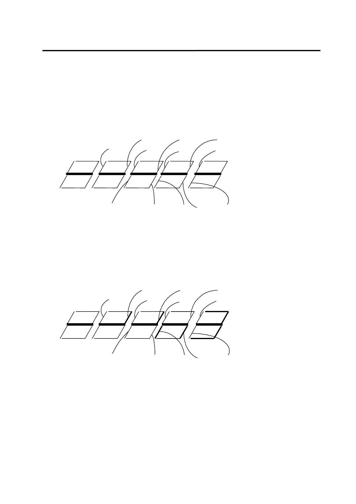
6.2.2 Mount loader signal display
The following figure shows magnified 7segment of the mount loader.
Each segment of the mount loader's 7segment has its own meaning.
The part above the solid line indicates the contact input status, while the part below the solid
line, the contact output status. The current status is displayed by each segment being turned
on or off.
SVONEN
SPD1
SPD2
SPD3
DIR
P/PI
CCWLIM
CWLIM
TLIM
ESTOP
STOP
ALMRST
Contact input
Contact output
BRK
INSPD/INPOS
ZSPDRDY
TRQOUT
ALARM
A_CODE0
A_CODE1
A_CODE2
From the following figure, the segments indicated in thick line are those turned on.
Segments can be displayed as follows assuming the I/O status is the same as explained in
section 6.8.1. In other words, the status which is displayed as "1" on digital loader is displayed
by the segment on the mount loader being turned on.
SVONEN
SPD1
SPD2
SPD3
DIR
P/PI
CCWLIM
CWLIM
TLIM
ESTOP
STOP
ALMRST
Contact input
Contact output
BRK
INSPD/INPOS
ZSPDRDY
TRQOUT
ALARMA_CODE0
A_CODE1
A_CODE2