x.Spot ™User Manual xv
List of Figures
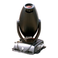
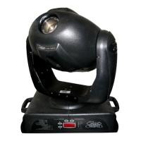
Figure 1-1 x.Spot Fixture Components .................................................................................... 1-1
Figure 1-2 Module Interleaving in Standard x.Spot™ fixture ................................................ 1-2
Figure 1-3 x-Spot Dimensions ................................................................................................... 1-5
Figure 2-1 Removing and replacing the bezel ......................................................................... 2-1
Figure 2-2 Removing handles and side wings .......................................................................... 2-3
Figure 2-3 Baseplate configuration for standard truss sizes .................................................. 2-4
Figure 2-4 XLR 5-pin connector ................................................................................................2-7
Figure 2-5 Linking x.Spot fixtures ............................................................................................2-8
Figure 2-6 Data cable terminator ..............................................................................................2-8
Figure 2-7 The x.Spot menu system navigation buttons ....................................................... 2-11
Figure 3-1 Front panel display .................................................................................................. 3-2
Figure 3-2 x.Spot Menu System Overview ............................................................................... 3-5
Figure 3-3 Edit Scene Menu Options in Standard x.Spot ....................................................... 3-9
Figure 3-4 Assigning timing to a scene .................................................................................. 3-12
Figure 3-5 Automatic Display Invert feature. ........................................................................ 3-18
Figure 4-1 Synchronized Playback Example ........................................................................... 4-3
Figure 4-2 Example of synchronized playback. ....................................................................... 4-3
Figure 4-3 x.Spot color wheel assembly ............................................................................... 4-10
Figure 4-4 Static Color Wheel positions ............................................................................... 4-11
Figure 4-5 Wheels in the Dual Rotating Gobos module ........................................................ 4-13
Figure 4-6 Rotating Gobo 2 Lithopatterns ............................................................................. 4-16
Figure 5-1 Removing and replacing the bezel ......................................................................... 5-1
Figure 5-2 Locate and access fuses. .......................................................................................... 5-2
Figure 5-3 Replacing the lamp .................................................................................................. 5-4
Figure 5-4 Lamp optimization screws ...................................................................................... 5-6
Figure 5-5 Driver board configurations. ................................................................................... 5-6
Figure 5-6 Replacing a 2-phase driver board. .......................................................................... 5-7
Figure 5-7 Installing/Replacing Slot 3 Module. ........................................................................ 5-8
Figure 5-8 Installing/Removing Slot 2 Module. ....................................................................... 5-9
Figure 5-9 Removing/Installing Slot 3 module ....................................................................... 5-10
Figure 5-10 Removing the Static Color Wheel. ...................................................................... 5-11
Figure 5-11 Replacing Static Color Wedges .......................................................................... 5-11
Figure 5-12 Accessing Dichroic wedges in Static Color Wheel. ........................................... 5-12
Figure 5-13 Replacing a lithopattern or effects glass in a rotating gobo wheel. ................. 5-13
Figure 5-14 Replacing Static lithopatterns. ............................................................................ 5-14