x.Spot ™ User Manual Setup and Configuration 2-7
2
Test each cable with a voltage/ohm meter (VOM) to verify correct polarity and to
make sure that the negative and positive pins are not grounded or shorted to the
shield or to each other.
Caution: Do not connect anything to the ground lug on the XLR connectors. Do
not connect or allow contact between the common (cable shield) and
the fixture’s chassis ground. Grounding the common could cause a
ground loop and/or erratic behavior.
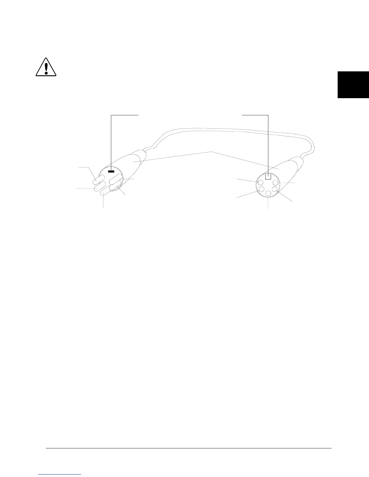
Figure 2-4 XLR 5-pin connector
Setting up the Link
To link one or more fixtures to a DMX controller as shown in Figure 2-5:
1. Connect the male XLR connector of a DMX Data cable to the controller’s DMX
Data Out connector.
2. Connect the Data cable’s female XLR connector to the Data In connector of the
first (or next) fixture on the DMX link.
3. Continue linking the remaining fixtures connecting a cable from the Data Out
connector of each fixture to the Data In connector of the next fixture on the link.
4. Connect a male terminator to the Data Out connector of the last fixture in the
link (see “Constructing a Terminator” on page 2-8). For information on obtaining
a terminator, see “Optional Accessories” on page 1-4.
positive
(data true)*
negative
(data
complement)*
Common
(cable shield)
2
1
3
Male XLR Connector
Female XLR Connector
positive
(data true)
negative
(data
complement)
XLR shell
Common
(cable shield
1
2
3
4
5
5
4
positive
(data true)*
negative
(data complement)*
negative
(data
complement)
positive
(data true)
*This data line is not used b
the fixture
but allows data to
ass throu
h the fixture.
Grounding lug (inside XLR shell)