5-6 General Maintenance x.Spot ™User Manual
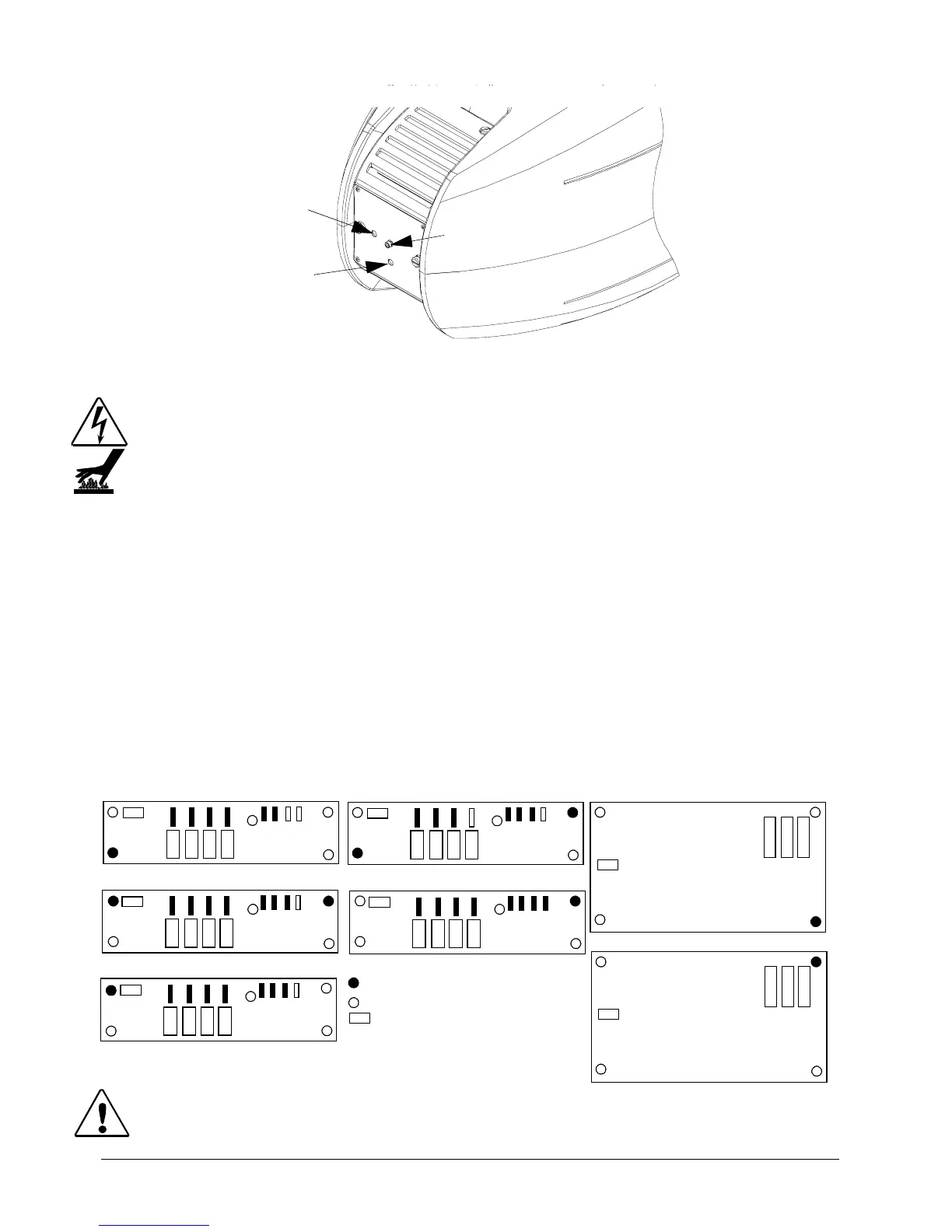
Figure 5-4 Lamp optimization screws
Replacing a Driver Board
Warnings: Disconnect power before servicing.
Equipment surfaces may reach temperatures up to 130° C (266° F). Allow the
fixture to cool before handling.
The standard x.Spot fixture is designed with two basic types of motor driver boards:
1. Interchangeable 2-phase boards drive the motors for each of the user-configured
modules, and the Focus/Frost/Zoom functions.
2. Interchangeable 3-phase pan and tilt driver boards.
Functional identification is accomplished with configuration of standoffs and contact
screws that allow for position- specific board addressing, see Figure 5-5
Figure 5-5 Driver board configurations.
Caution: The fixture will not function correctly if contact screws are missing
from driver boards.
x
y
z
IDC
IDC
IDC
IDC
Color Mix A (Slot 1A)
Color Mix B (Slot 1B)
Dual Rotating Gobo (Slot 2)
Gobo/Iris (Slot 3)
Focus/Frost/Zoom
screw position
IDC
connector
standoff position
Pan
Tilt
3-Phase Motor Driver Boards
2-Phase Motor Driver Boards
IDC
IDC
IDC