1-4
Understanding LED Indicators
Trackspot User Manual
Understanding LED Indicators
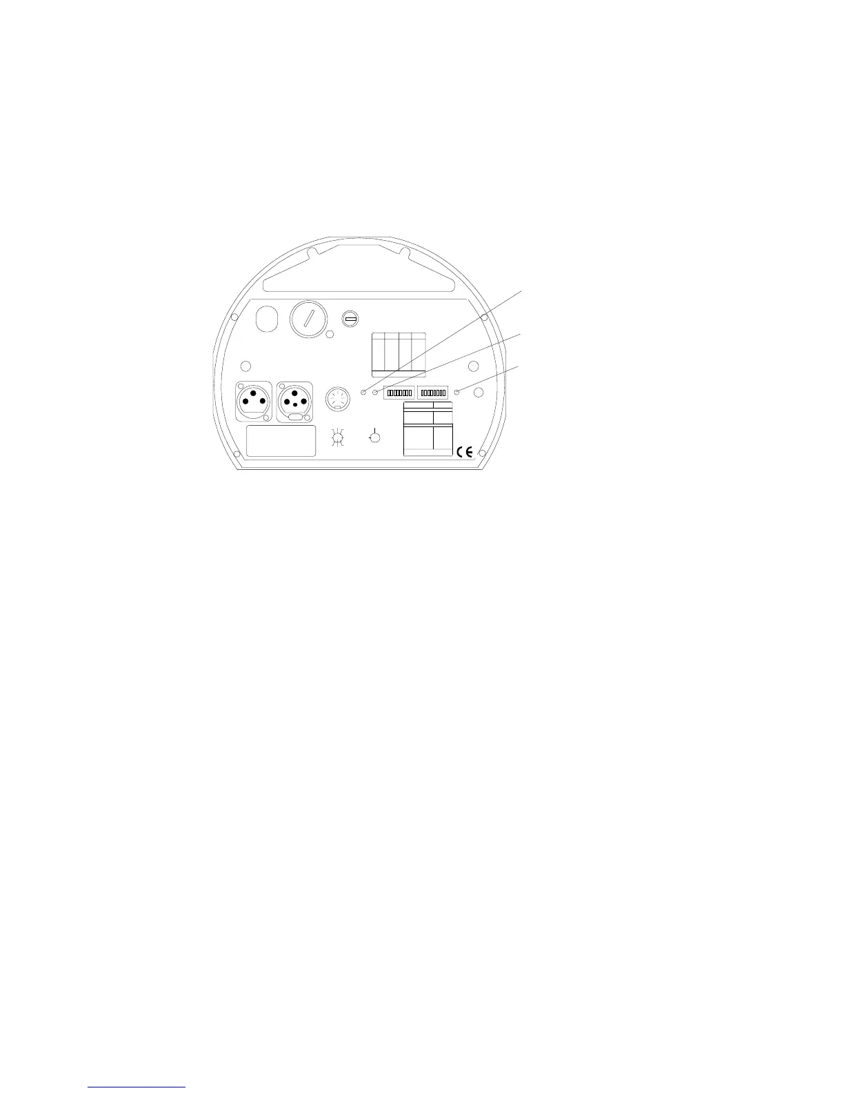
This section describes the LEDs (Light Emitting Diode) on the
Trackspot rear panel: Fan, Enable, and Audio (see Figure 1-4). If you
are experiencing problems with your Trackspot fixture, these LEDs
may provide insight on where the problem is originating. See “” on
page 4-1 for possible solutions to LED-related symptoms.
Fan LED
The red Fan LED monitors the voltage to the cooling fan. The Fan LED
illuminates when the fixture is first powered up, and stays illuminated
for two minutes after the lamp is extinguished. Trackspot comes
equipped with thermal overload protection to automatically extinguish
the lamp if the maximum temperature inside the fixture is exceeded. If
the fixture overheats, the Fan LED will flash four times, pause, and
repeat.
Enable LED
The yellow Enable LED monitors the power applied to the motors. The
Enable LED should be illuminated whenever the fixture is ON. If the
logic board is not receiving the 24 volts required to operate the fixture,
the Enable LED will not illuminate.
Audio LED
The green Audio LED monitors the fixture’s response to sound. The
Audio LED illuminates when the fixture is ON and ambient bass is
registered, regardless of the configuration. (If the fixture is not
programmed to receive audio bass frequencies, the sound trigger is
ignored.)
Figure 1-4. LED location on the rear panel
Fan LED
Enable LED
Audio LED
FI XT URE MODE SWI TCHES 1-2
NORMAL RUN
SELF TEST
SET- UP
NONE
1
2
1,2
LIGHTWAVE CONTROL
DMX 1-2 56
DMX 257-512
ANALOG
AUDIO ( SLAVE)
AUDIO ( MASTER)
PAN INVERT
TI LT I NVE RT
NONE
5
4
4,5
3
6
7
AUDIO
MIC
PERSONALITY
ADDRESS
ENABLEFAN
ANALOG IN
DATA OUTDATA IN
2209 WEST BRAKER LANE, AUST IN, T EXAS U.S.A.
LI GHTWAVE RESE ARCH
CONTROL MODE SWITCHES 3-8
8
PERSONALITY SWITCHES
ON
PLEASE CONSU LT USER MANUAL
FOR FURTHER INFORMATION
LA MP SAVE
PLEASE CONSU LT USER MANUAL
FOR FURTHER INFORMATION
ON
SWITCHES
ON
SWITCHESADDRESS ADDRESS
1,2, 3,524
2,3, 523
1,3, 522
3,521
1,2, 520
2,519
1,518
517
1,2, 3,416
2,3, 415
1,3, 414
3,413
1,2, 412
2,411
1,410
409
1,2, 308
2,307
1,306
305
1,204
203
102
none01
FUSE
VOLTAG E SELECT
WARNING: CH ANGE V OLTAGE SE LECT ONLY WI TH POWER REMOVED.
CAUTION: HOT REMOVE POW ER BEFORE RELAMPING
WARNING: NOT FOR RESIDENTIAL USE. TO REDUCE THE RIS K OF
FIRE OR ELECTRIC SHOCK, DO NOT EXPOSE TO RAIN OR MOISTURE,
NO USER SE RVI C EA BL E PA RTS INSIDE. RE FER SERVICI NG TO
QUALIFIED SE RVICE PE RSONNEL. FOR S AFE OP ERATION CONSU LT
USER MANUAL.
(UNREG.)
OUT
INPUT
SPECIAL ANALOG
CONSULT USERS MANUAL
FOR FUTH ER INFORMATIO N
24 V DC
SHUT TER
MS P EED
TI L T
GOB O DIM
PAN
COLOR
8
2
4
1
67
3
5
GND
5
3
76
1
4
2
8
ANALOG
0-10 V
GND
tracks pot
14 0
20 0
12 0
24 0
10 0
22 0
MODEL
SERIAL
FACTORY SET VAC
WATTS HZ
DATE QC