Trackspot User Manual
Enabling the Control Mode
2-3
2
Enabling the Control Mode
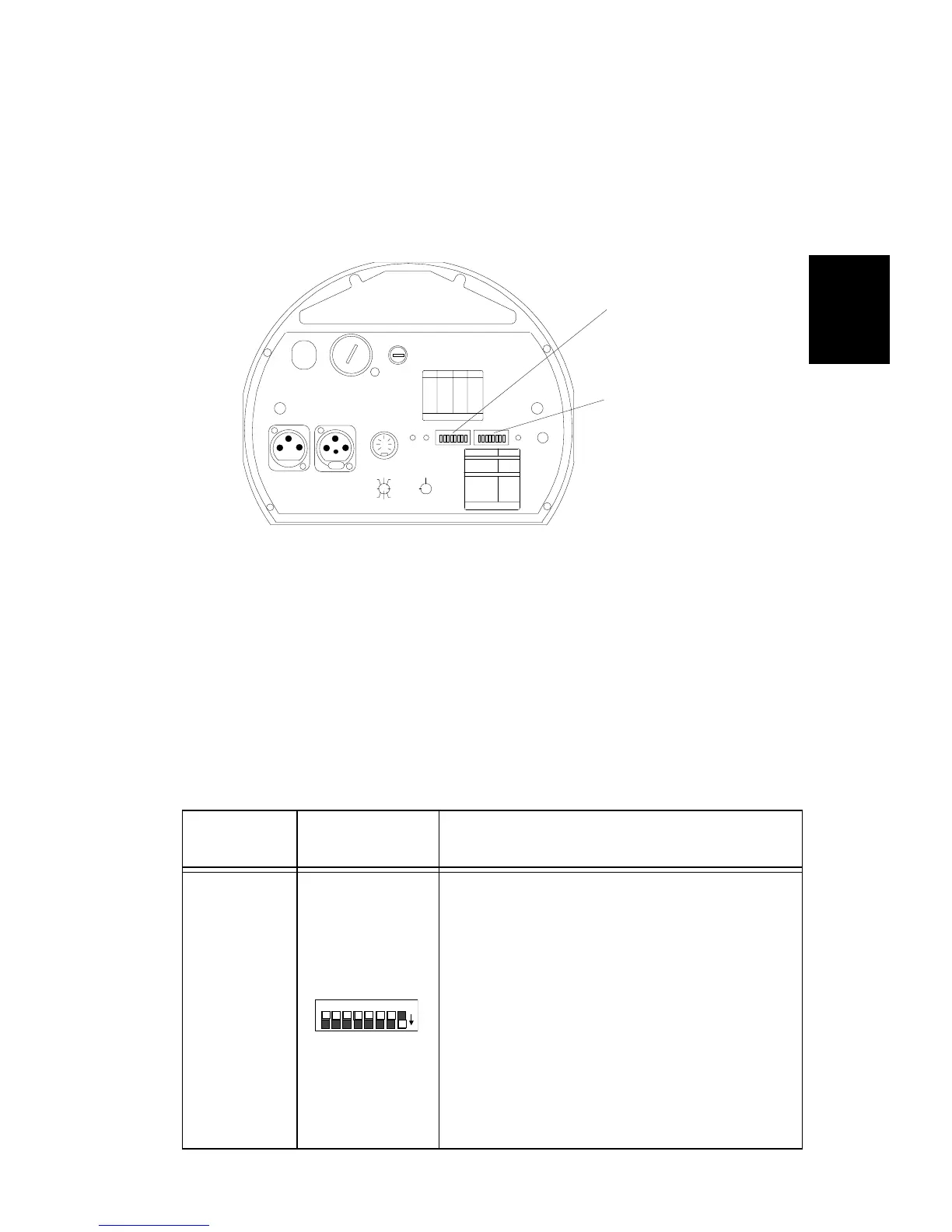
Once you determine which control mode to use, you must set the
fixture’s DIP switches to enable each Trackspot for that control mode
and to assign fixture order (or starting channel). The personality and
address DIP switches (all factory set OFF) are located on the rear panel
of the fixture (see Figure 2-1).
For sample personality and address switch settings in each control
mode, see “Linking the Fixtures” on page 2-12.
Personality Switches
The personality switch settings determine the fixture’s operating mode
and/or control mode. See Table 2-2 below for a detailed description of
personality switch settings. For a quick-reference table of personality
switch settings, see “Personality Switch Settings” on page C-1.
Table 2-2. Personality switch settings - operating modes
Operating
Modes
Personality
Switches ON
Description
Self Test
Starts an internal self-diagnostic routine
which verifies that the major functions of
the fixture (pan, tilt, gobo wheel, color
wheel, and shutter) are working properly.
The fixture performs its homing procedure
once (you will hear clattering sounds as the
shutter and mirror seek their home
position) and then repeats its self-test until
you set switch 1 OFF.
Note: Although a controller is not required
for the self-test, setting personality switch 1
ON will override any controller that might
be attached to the fixture.
FI XT URE MODE SWI TCHES 1-2
NORMAL RUN
SELF TEST
SET- UP
NONE
1
2
1,2
LIGHTWAVE CONTROL
DMX 1-256
DMX 257-512
ANALOG
AUDIO ( SLAVE)
AUDIO ( MASTER)
PAN INVERT
TI LT I NVE RT
NONE
5
4
4,5
3
6
7
AUDIO
MIC
PERSONALITY
ADDRESS
ENABLEFAN
ANALOG IN
DATA OUTDATA IN
2209 WEST BRAKER LANE, AUST IN, T EXAS U.S.A.
LI GHTWAVE RESE ARCH
CONTROL MODE SWITCHES 3-8
8
PERSONALITY SWITCHES
ON
PLEASE CONSU LT USER MANUAL
FOR FURTHER INFORMATION
LA MP SAVE
PLEASE CONSU LT USER MANUAL
FOR FURTHER INFORMATION
ON
SWITCHES
ON
SWITCHESADDRESS A DDRESS
1,2,3,524
2,3, 523
1,3, 522
3,521
1,2, 520
2,519
1,518
517
1,2,3,416
2,3, 415
1,3, 414
3,413
1,2, 412
2,411
1,410
409
1,2, 308
2,307
1,306
305
1,204
203
102
none01
FUSE
VOLTAG E SELECT
WARN I N G: C H ANGE V OL T A GE SE LE CT ON LY W I TH P OWE R R E M OV ED .
CAUTION: HOT REMOVE POW ER BEFORE RELA MPING
WARNING: NOT FOR RESIDENTIAL USE. TO REDUCE THE RIS K OF
FIRE OR ELECTRIC SHOCK, DO NOT EXPOSE TO RAIN OR MOISTURE,
NO USER SE RVI C EA BL E PA RTS INSIDE. RE FER SERVICI NG TO
QUALIFIED SE RVICE PE RSONNEL. FOR S AFE OP ERATION CONSULT
USER MANUAL.
(UNREG.)
OUT
INPUT
SPECIAL ANALOG
CONSULT USERS MANUAL
FOR FUTH ER INFORMATIO N
24 V DC
SHUT TER
MS P EED
TI L T
GOB O DIM
PAN
COLOR
8
2
4
1
67
3
5
GND
5
3
76
1
4
2
8
ANALOG
0-10 V
GND
tracks pot
14 0
20 0
12 0
24 0
10 0
22 0
®
personality switches
address switches
Figure 2-1. Address and personality DIP switches
on
PERSONALITY
8 7 6 5 4 3 2 1