Trackspot User Manual
Obtaining Cabling and Terminators
2-11
2
Constructing Cabling
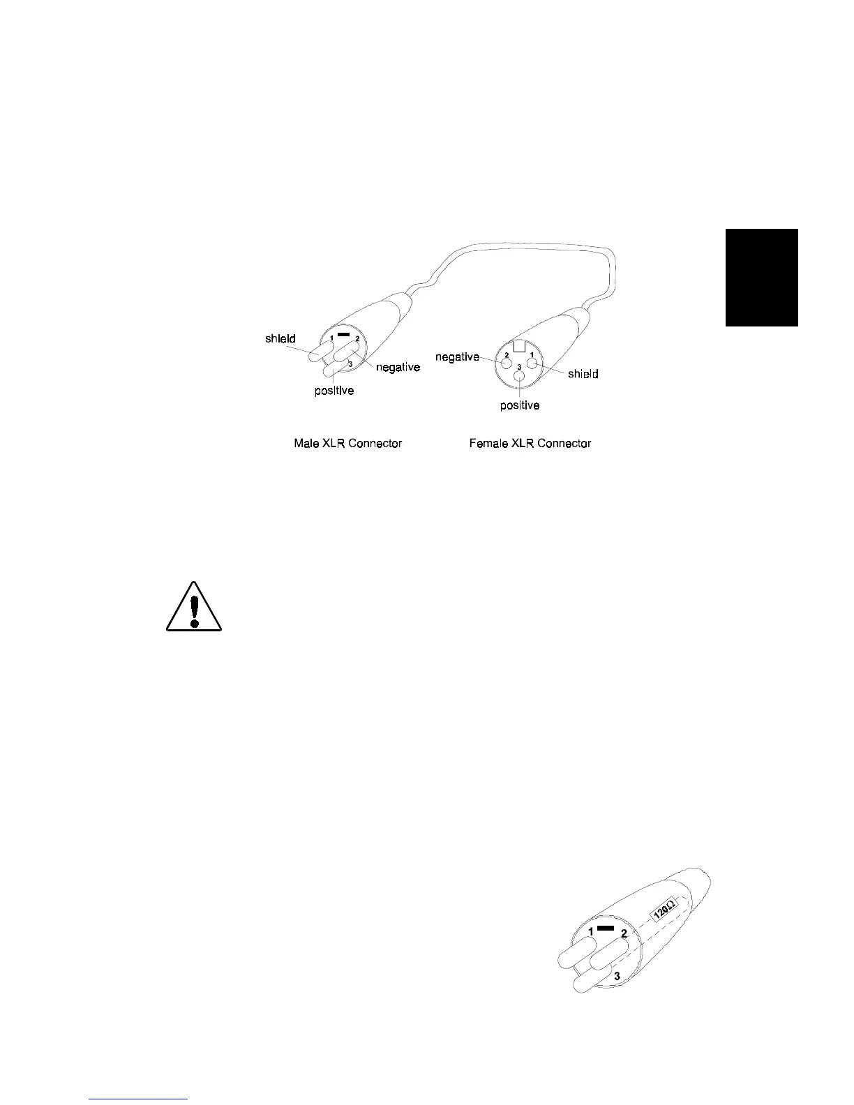
If you need to construct cabling, you must use a shielded, two-
conductor cable with a male 3-pin XLR connector on one end and a
female 3-pin XLR connector on the other end. Pin one is the shield
(ground), pin two is the data complement (negative), and pin three is
the data true (positive) (see Figure 2-5). For more information on
cabling and connector specifications, see “Specifications” on page
Intro-4.
You should test each cable with a voltage/ohm meter (VOM) to verify
correct polarity and to make sure that the negative and positive pins
are not grounded or shorted to the shield or to each other. Also, make
sure that pin 1 is shielded.
Caution: Do not use the ground lug on the XLR
connectors. Do not connect the shield to
ground or allow contact to ground.
Grounding the shield could cause a ground
loop and/or erratic behavior.
Constructing Terminators
If you chose to use standard analog control, you do not need to attach a
terminator to the last device on each link. However, for all other
control modes, the last device on each link must have a 120 ohm, 1/4
watt (minimum) terminator attached to its Data Out connector.
You can construct terminators by following the instructions below:
1. Obtain a male XLR connector.
2. Disassemble the connector.
3. Solder a 120 ohm resistor, minimum of 1/4
watt, between pins 2 and 3 (see Figure 2-6).
4. Reassemble the XLR connector.
5. Install the terminator in the Data Out
connector of the last fixture in the link.
Figure 2-5. XLR 3-pin connectors
Figure 2-6. Data
cable terminator