Trackspot User Manual
Installing Remote Enable/Disable
2-7
2
SPST Switch
Note: Connect only the master fixture to the SPST switch.
To install an SPST switch:
1. Unplug the fixture.
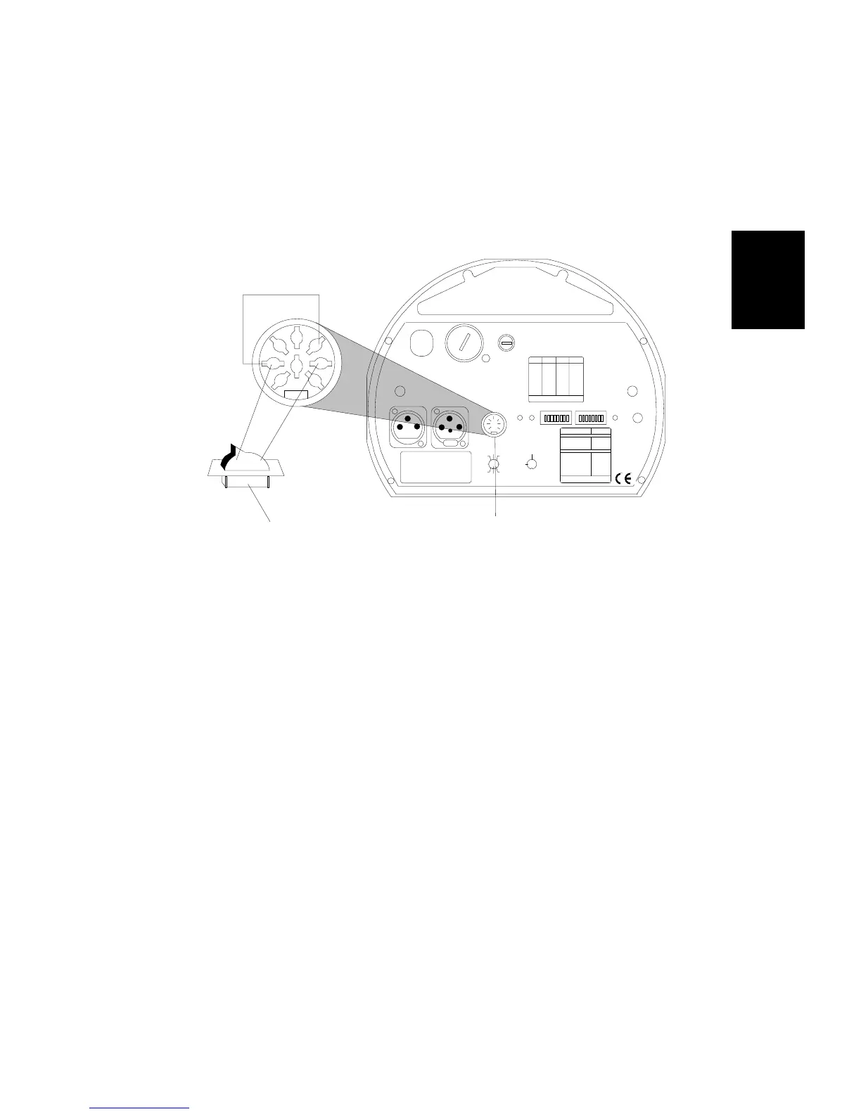
2. Locate the female Analog In connector on the rear panel of the
master Trackspot fixture (see Figure 2-2).
3. Connect DIN pin 1 and pin 5 together (see Figure 2-2). You can
connect these pins either at the fixture or in the male 8-pin DIN
connector.
4. Connect DIN pin 1 and pin 3 to the SPST switch (see Figure 2-2).
When correctly connected to the SPST switch, the fixtures will be
enabled when the circuit is closed and disabled when the circuit is
open.
External Voltage Source
Note: Connect only the master fixture to the external voltage
source.
To install an external voltage source:
1. Unplug the fixture.
2. Locate the Analog In female connector on the rear panel of the
master Trackspot fixture (see Figure 2-2).
3. Connect analog DIN pin 1 and pin 5 together (see Figure 2-2). You
can connect these pins either at the fixture end or in the male 8-pin
DIN connector.
Figure 2-2. Connecting a remote enable/disable switch to
the master fixture
remote SPST switch
OFF ON
Analog In Connector
1 3
5
6
7
4
2
8
FI XT URE MODE SWI TCHES 1-2
NORMAL RUN
SELF TEST
SET- UP
NONE
1
2
1,2
LIGHTWAVE CONTROL
DMX 1-2 56
DMX 257-512
ANALOG
AUDIO ( SLAVE)
AUDIO ( MASTER)
PAN INVERT
TI LT I NVE RT
NONE
5
4
4,5
3
6
7
AUDIO
MIC
PERSONALITY
ADDRESS
ENABLEFAN
ANALOG IN
DATA OUTDATA IN
2209 WEST BRAKER LANE, AUST IN, T EXAS U.S.A.
LI GHTWAVE RESE ARCH
CONTROL MODE SWITCHES 3-8
8
PERSONALITY S WITCHES
ON
PLEASE CONSU LT USER MANUAL
FOR FURTHER INFORMATION
LA MP SAVE
PLEASE CONSU LT USER MANUAL
FOR FURTHER INFORMATION
ON
SWITCHES
ON
SWITCHESADDRESS ADDRESS
1,2,3,524
2,3, 523
1,3, 522
3,521
1,2, 520
2,519
1,518
517
1,2,3,416
2,3, 415
1,3, 414
3,413
1,2, 412
2,411
1,410
409
1,2, 308
2,307
1,306
305
1,204
203
102
none01
FUSE
VOLTAG E SELECT
WARNING: CH ANGE V OLTAGE SE LECT ONLY WI TH POWER REMOVED.
CAUTION: HOT REMOVE POW ER BEFORE RELAMPING
WARNING: NOT FOR RESIDENTIAL USE. TO REDUCE THE RIS K OF
FI RE OR E LEC TRI C SH OCK, D O NO T E XPOS E TO R AIN O R MOI STUR E,
NO USER SERVI CEABLE PARTS INSIDE. RE FER S ERVICI NG TO
QUALIFIED SE RVICE PE RSONNEL. FOR S AFE OP ERATION CONSU LT
USER MANUAL.
(UNREG.)
OUT
INPUT
SPECIAL ANALOG
CONSULT USERS MANUAL
FOR FUTH ER INFORMATIO N
24 V DC
SHUT TER
MS P EED
TI L T
GOB O DIM
PAN
COLOR
8
2
4
1
67
3
5
GND
5
3
76
1
4
2
8
ANALOG
0-10 V
GND
tracks pot
14 0
20 0
12 0
24 0
10 0
22 0
MODEL
SERIAL
FACTORY SET VAC
WATTS HZ
DATE QC