EasyManuals Logo

HIMA Himax X-COM 01 User Manual

HIMA Himax X-COM 01
42 pages
To Next Page IconTo Next Page
To Previous Page IconTo Previous Page
Page #13 background imageLoading...
Page #13 background image
X-COM 01 3 Product Description
HI 801 011 E Rev. 5.00 Page 13 of 42
3.4 Structure
The module is composed of:
Processor System
Ethernet Switch
Ethernet and fieldbus interfaces on the connector board.
The module is equipped with LEDs to indicate the status, see Chapter 3.4.3.
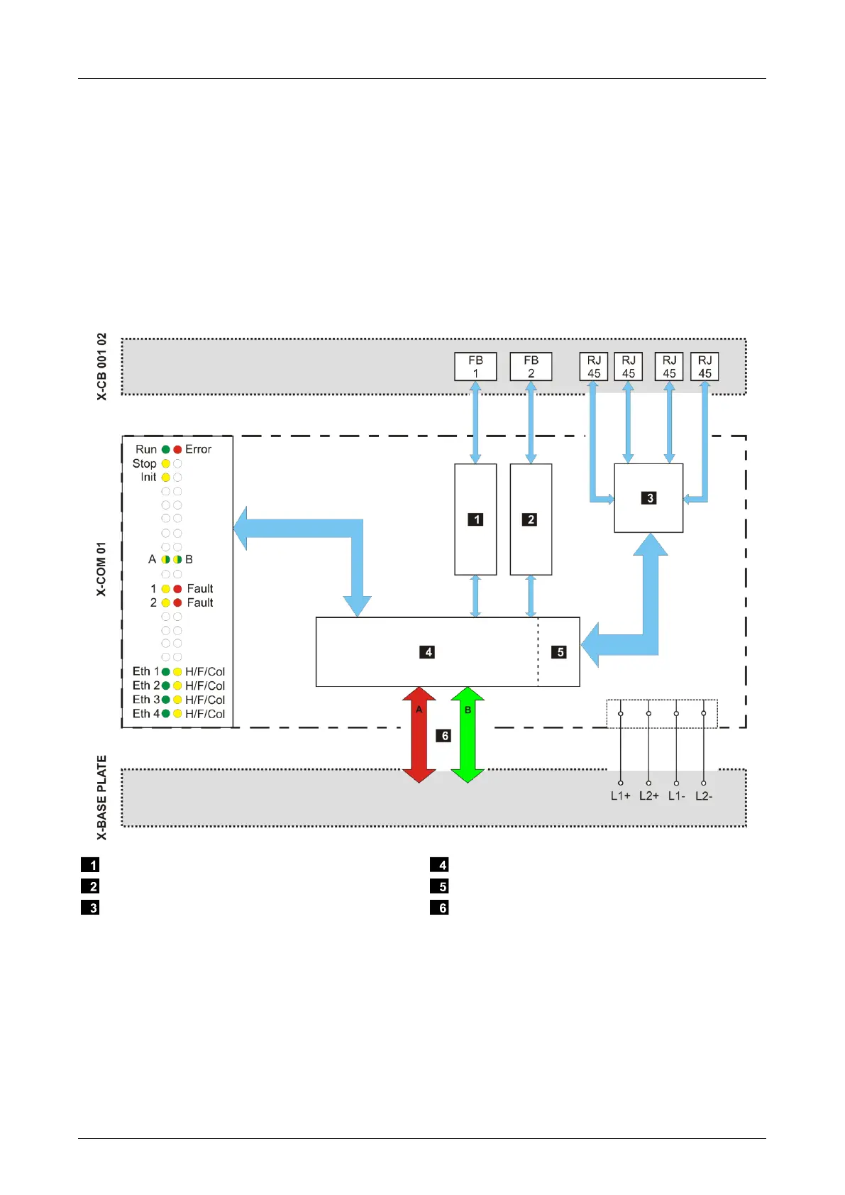
3.4.1 Block Diagram
The following block diagram illustrates the structure of the module.
Fieldbus submodule 1
Fieldbus submodule 2
Ethernet Switch
Processor System
Ethernet Interface
System Busses
Figure 2: Block Diagram

Table of Contents

Questions and Answers:

Question and Answer IconNeed help?

Do you have a question about the HIMA Himax X-COM 01 and is the answer not in the manual?

HIMA Himax X-COM 01 Specifications

General IconGeneral
BrandHIMA
ModelHimax X-COM 01
CategoryConference System
LanguageEnglish

Related product manuals