3 Product Description X-COM 01
Page 16 of 42 HI 801 011 E Rev. 5.00
The LEDs on the module are divided into three groups:
Module status indicators (Run, Error, Stop, Init)
System bus indicators (A, B)
Fieldbus indicators (1, 2, Fault)
Communication indicators (Ethernet)
When the supply voltage is switched on, a LED test is performed and all LEDs are briefly lit.
Definition of blinking frequencies
The following table defines the blinking frequencies of the LEDs:
Long (approx. 600 ms) on, long (approx. 600 ms) off
Short (approx. 200 ms) on, short (approx. 200 ms) off, short (approx. 200 ms)
on, long (approx. 600 ms) off
Ethernet communication: Blinking synchronously with data transfer
Table 8: Blinking Frequencies of LEDs
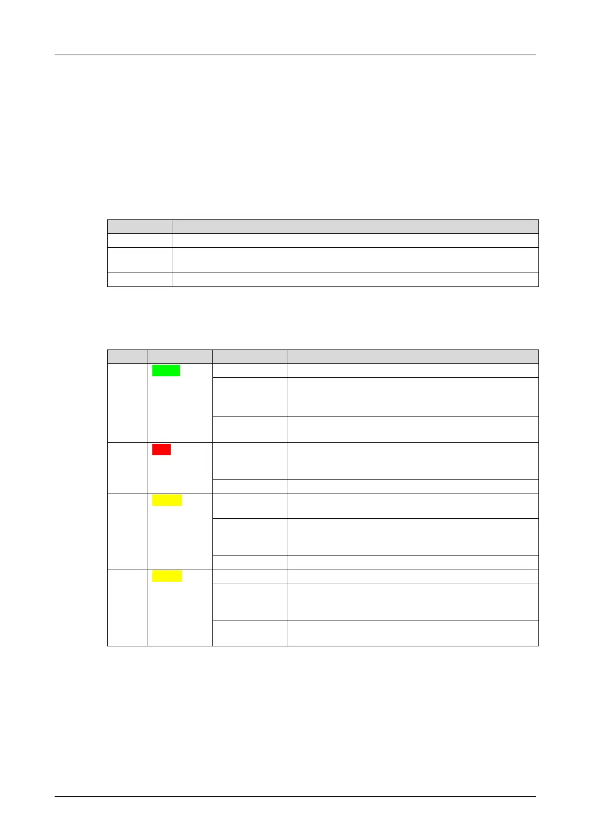
3.4.4 Module Status Indicators
These LEDs are located on the front plate, on the upper part of the module.
Module in RUN, normal operation
Module state:
STOP/OS_DOWNLOAD or
OPERATE (only with processor modules)
Module not in RUN,
observe the other status LEDs
Internal module faults detected by self-tests, e.g.,
hardware or voltage supply.
Fault while loading the operating system
Module state:
STOP / VALID CONFIGURATION
Module state:
STOP / INVALID CONFIGURATION or
STOP / OS_DOWNLOAD
Module not in STOP, observe the other status LEDs
Module state:
LOCKED or
STOP / LOADING OS
Module state: neither INIT nor LOCKED, observe the
other status LEDs
Table 9: Module Status Indicators