3 Product Description X-COM 01
Page 20 of 42 HI 801 011 E Rev. 5.00
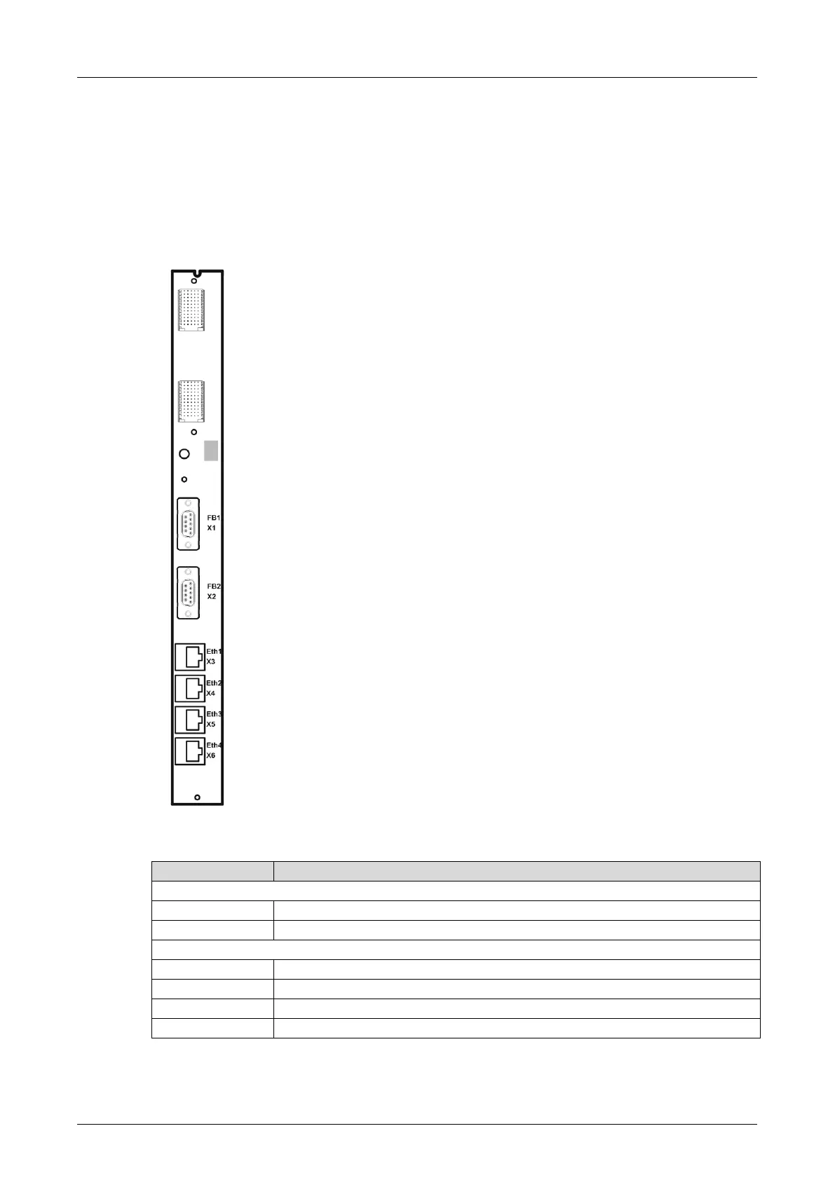
3.6 Connector board
The connector board connects the module to other systems using the Ethernet and fieldbus
interfaces. Each module forms a functional unit with the connector board. The connector board
for the module is designated as X-CB 001 02. The connector board must be inserted into the
appropriate slot prior to mounting the module on the base plate.
3.6.1 Pin Assignment
The interface designation is printed on the connector board.
Figure 5: Connector Board
Connection for fieldbus, the protocol depends on the Fieldbus Submodule
Connection for fieldbus, the protocol depends on the Fieldbus Submodule
Table 15: Interfaces of X-CB 001 02