4 Start-up X-COM 01
Page 22 of 42 HI 801 011 E Rev. 5.00
4 Start-up
This chapter describes how to install and configure the module. For more information, refer to
HIMax system manual (HI 801 001 E).
4.1 Mounting
Observe the following points when mounting the module:
Only operate the module with the appropriate fan components. For more information, see the
System Manual (HI 801 001 E).
Only operate the module with the suitable connector board. For more information, see
Chapter 3.6.
4.2 Mounting and Removing the Module
When replacing an existing module or mounting a new one, follow the instructions given in this
chapter.
When removing the module, the connector board remains in the HIMax base plate. This saves
additional wiring effort since all field terminals are connected via the connector board of the
module.
4.2.1 Mounting a Connector Board
Tools and utilities
Screwdriver, cross PH 1 or slotted 0.8 x 4.0 mm
Matching connector board
To install the connector board
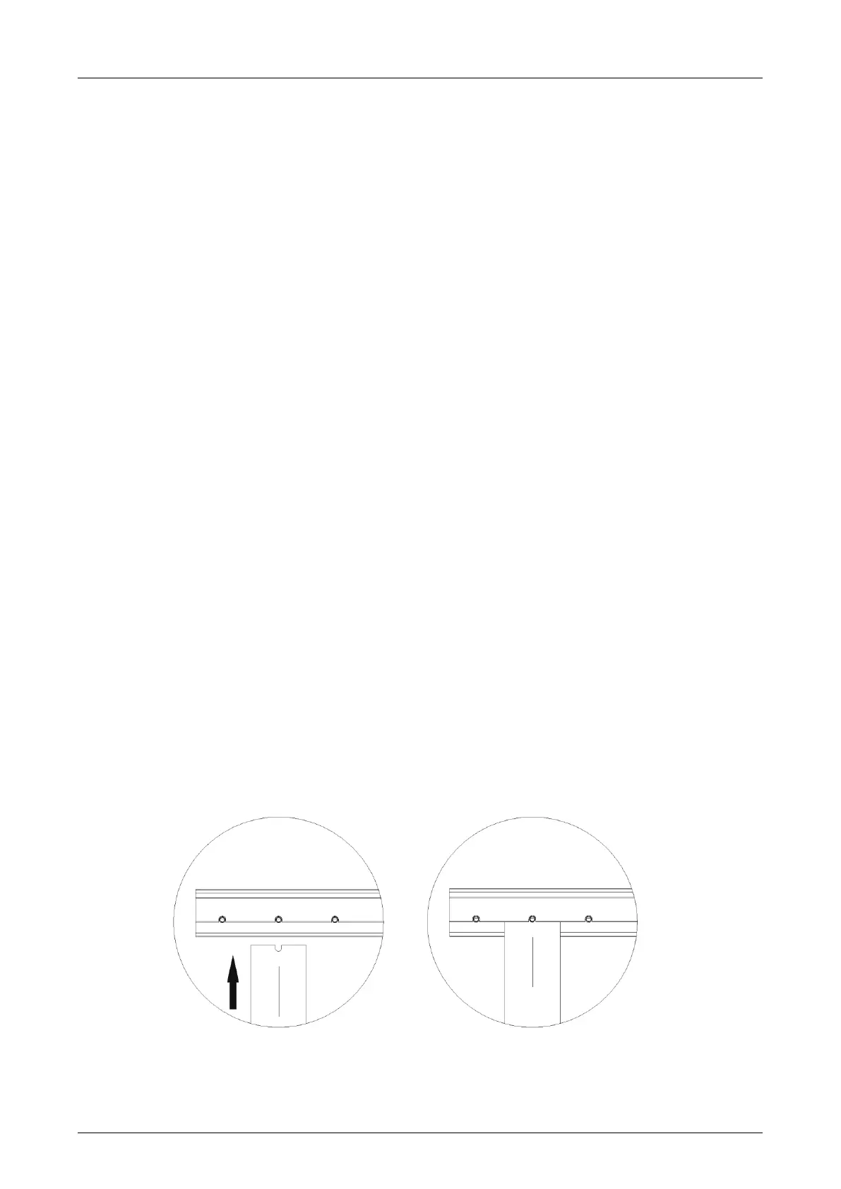
1. Insert the connector board into the guiding rail with the groove facing upwards (see following
figure). Fit the groove into the guiding rail pin.
2. Place the connector board on the cable shield rail.
3. Secure the captive screws to the base plate. First screw in the lower screws than the upper
ones.
To remove the connector board
1. Release the captive screws from the base plate.
2. Carefully lift the lower section of the connector board from the cable shield rail.
3. Remove the connector board from the guiding rail.
Figure 6: Example of how to Insert the Mono Connector Board