X-COM 01 3 Product Description
HI 801 011 E Rev. 5.00 Page 17 of 42
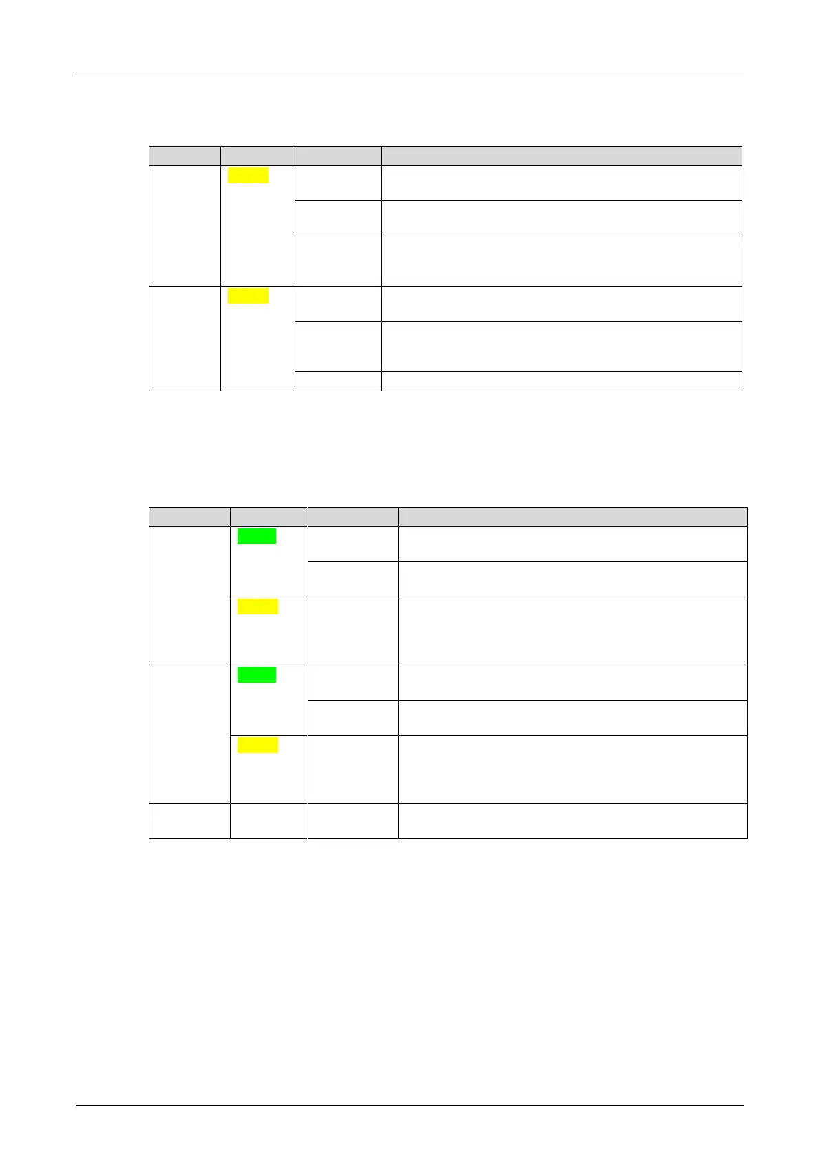
3.4.5 Redundancy indicators
The LEDs are located below the module status indicators.
At least one non-redundant fieldbus protocol is
configured.
A fieldbus protocol configured for redundant operation is
not operating redundantly.
All fieldbus protocols configured for redundant
operation are operating redundantly.
No non-redundant fieldbus protocols are running.
All fieldbus protocols configured for redundant operation
are operating redundantly to the partner module.
Synchronization
The redundant partner of at least one redundant
fieldbus protocol is missing.
No redundant fieldbus protocol is configured.
Table 10: Redundancy Indicators
3.4.6 System Bus Indicators
The system bus LEDs are labeled Sys Bus.
Physical and logical connection to the system bus
module in slot 1.
No physical connection to the system bus module in
slot 1.
The physical connection to the system bus module in
slot 1 has been established.
No connection to a (redundant) processor module
running in system operation.
Physical and logical connection to the system bus
module in slot 2.
No physical connection to the system bus module in
slot 2.
The physical connection to the system bus module in
slot 2 has been established.
No connection to a (redundant) processor module
running in system operation.
Neither physical nor logical connection to the system
bus modules in slot 1 and slot 2.
Table 11: System Bus Indicators