29
___________________________________________________________________
Chapter 5 Advanced Measurement Functions
___________________________________________________________________
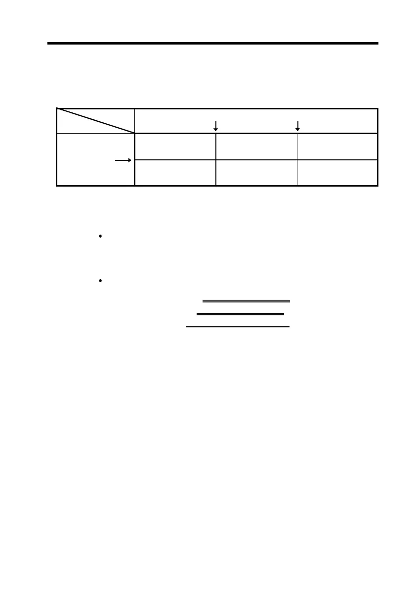
Resistance
Voltage
Lower resistance limit Upper resistance limit
LO IN HI
Voltage
comparison
value
LO
HI
WARNING
Amber *1
WARNING
Amber
FAIL
Red
PASS
Green
WARNING
Amber
FAIL
Red
*1 Voltage low and resistance low: amber flashing
Beeper sounds when the comparator result is WARNING or FAIL. (Refer to
Section 5.3, "Beeper On/Off Function")
5.1.3 Com
arator Decision Result Table
The decision result is indicated by the LEDs and by the
beeper, as shown in the following table.
A"PASS" result is shown by the green LED, a
"WARNING" by the amber LED, and a "FAIL" by the red
LED.
The boundary conditions are as follows.
Resistance LO ≦ Lower resistance limit < Resistance IN
Resistance IN ≦ Upper resistance limit
< Resistance HI
Voltage LO ≦ Voltage comparison value
< Voltage HI
●
Interpreting the comparator output table
Example 1
When the measured resistance is at or below the lower
resistance limit, and the measured voltage is greater than the
voltage comparison value (that is, resistance: LO and
voltage: HI), the LED for
PASS
(green) lights. The beeper
does not sound.
Example 2
When the measured resistance is greater than the lower
resistance limit and lower than the upper resistance limit
value, and the measured voltage is greater than the voltage
comparison value (that is, resistance: IN, voltage: HI) the
LED for
WARNING
(amber) lights and the beeper sounds.