45
___________________________________________________________________
Chapter 5 Advanced Measurement Functions
___________________________________________________________________
Is
R
1
R
2
V
IS
R
3
R
4
DC-elimination
capacitor
Constant current
source
Voltmeter
Resistance R
Resistance measurement circuit
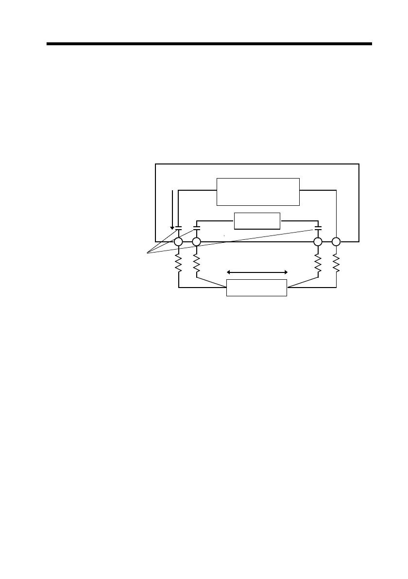
5.9 AC Four-Terminal Method
The 3550 uses the AC four-terminal method, so that
resistance measurement can be carried out with the resistance
of the leads, and the contact resistance between the object to
be measured and the leads canceled out. The following
figure shows the principle of the AC four-terminal
measurement method.
Values R1 to R4 are the resistances of the test leads plus
contact resistances.
An AC current (Is) is supplied from the
SOURCE
terminals of
the 3550 across the tested battery.
The voltage drop across the internal impedance of the battery
(V
IS
) is measured by the
SENSE
terminals. At this point,
since the
SENSE
terminals are connected to an internal
voltmeter with a high impedance, almost no current flows
through the resistances R2 and R3 which represent the lead
resistances and contact resistances.
As a result, there is almost no voltage drop across the
resistances R2 and R3. Thus the voltage drop due to the
lead resistances and contact resistances is very small, and
these can be canceled out.