iFLEX5 Boom Control System (BCS)
© Hirschmann Rev. I 05/22/17 190154_I.DOC
14.1.3.A Manual Mode Operation:
Primarily used for boom maintenance and function the boom in an unlikely event of a BCS
failure. In manual mode the boom is controlled by the section selector switch in the right
hand arm rest in the cab. When IM selected, crane electric provides full power to the extend
and retract proportional solenoids on the IM pilot operated 4-way directional control valve.
This means the telescoping action is controlled directly by moving the joystick or foot
operated treadle valve. The BCS does not control movement. Likewise when CM is selected,
crane electric provides full power to the extend and retract proportional solenoids on the CM
pilot operated 4-way directional control valve.
Note: In the event of an LMI error, overload, or A2B condition the proportional valves will be
not be energized unless the LMI bypass is activated, either from the central unit or console.
14.1.3.B Auto Mode Operation:
An extend or retract action is initiated by moving the joystick or foot operated treadle valve
causing hydraulic pilot pressure to activate an extend or retract pressure switch. The
pressure switch signals are seen as digital inputs to the BCS. As an example of extend from
fully retracted, the BCS realizes DI 19=1 (extend pressure switch on) and simultaneously
activates DO
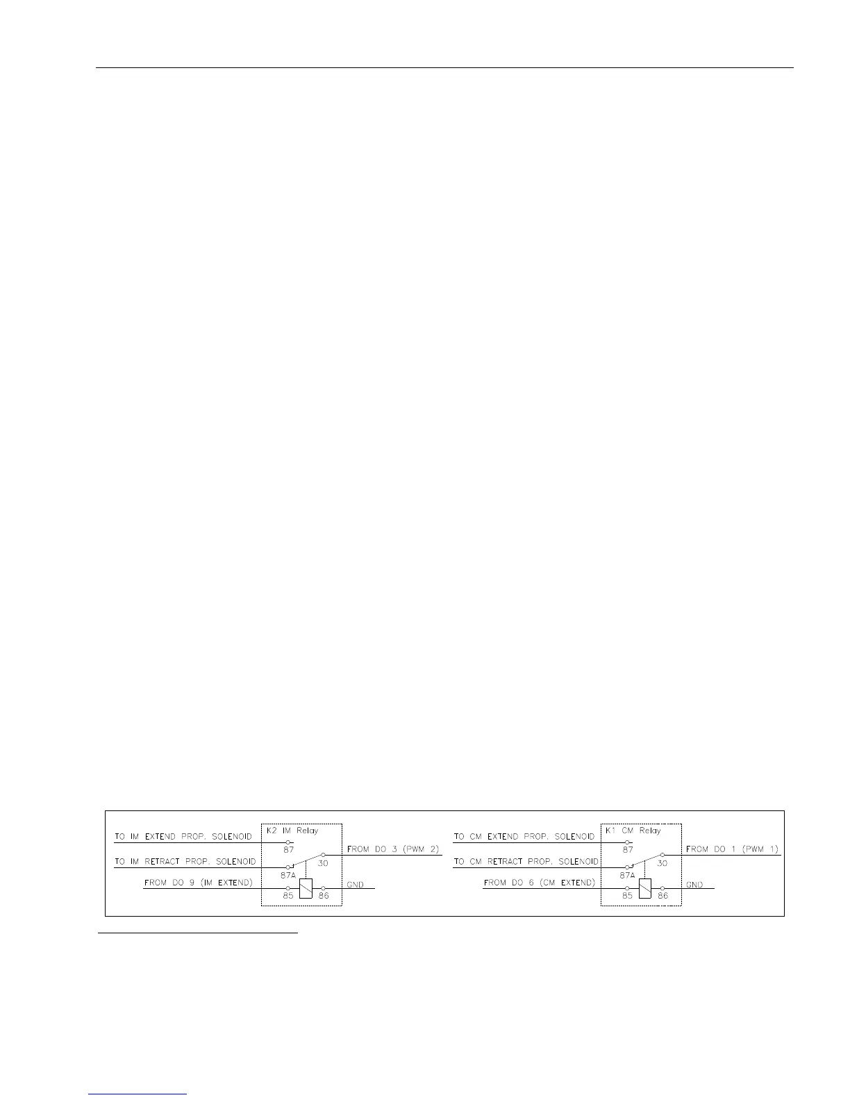
9 (IM extend) and DO 3 (PWM 2, IM proportional solenoid). DO 9 energizes a
relay in the BCS relay junction box assy to direct DO 3 to the IM pilot operated 4-way
directional control extend proportional solenoid. Figure 1 illustrates how DO 3 is directed to
the solenoid valve. DO 3 is a PWM output and ramps the output according to variables in the
data software. Ramp-up output is time based. When the IM section approaches a change
over point (change in sequence), DO 3 is ramped down according to variables in the data
software. Ramp-down output is percentage based. See table 1 and table 2 for sequencing
information. At the specified change over point, the BCS turns off DO 9 (IM extend) and
simultaneously turns on DO 6 (CM extend) and DO 1 (PWM 1, CM proportional solenoid).
DO 6 energizes a relay in the BCS relay junction box assy to direct DO 1 to the CM pilot
operated 4-way directional control extend proportional solenoid. DO 1 is a PWM output and
ramps the output according to variables in the data software. When the CM section
approaches a change over point DO 1 ouput is ramped down according to variables in the
data software. And so on. When retracting, the BCS realizes DO 18=1 (retract pressure
switch) and does not activate DO 6 or DO 9. DO 1 or DO 3 are activated based on the
current boom position.
figure 1
Refer to table 2 for digital output definitions