Table 3: Backup protection example data
Station Tap transformer 10 MVA
Type of fault Three phase fault
Object 1 = 10 kV Line A 2 = T1 10 kV 50/51 3 = 130 kV 87L
(ImaxAddDelay)
Setting 2 MVA 14 MVA 20 MVA
Characteristic IEC Extr.inverse, k=0.5, A=80,
p=2
IEC Norm.inverse k=0.12,
A=0.14, p=0.02
IEC Norm.inverse k=0.18,
A=0.14, p=0.02
High set stage 14 MVA - - - - - - - -
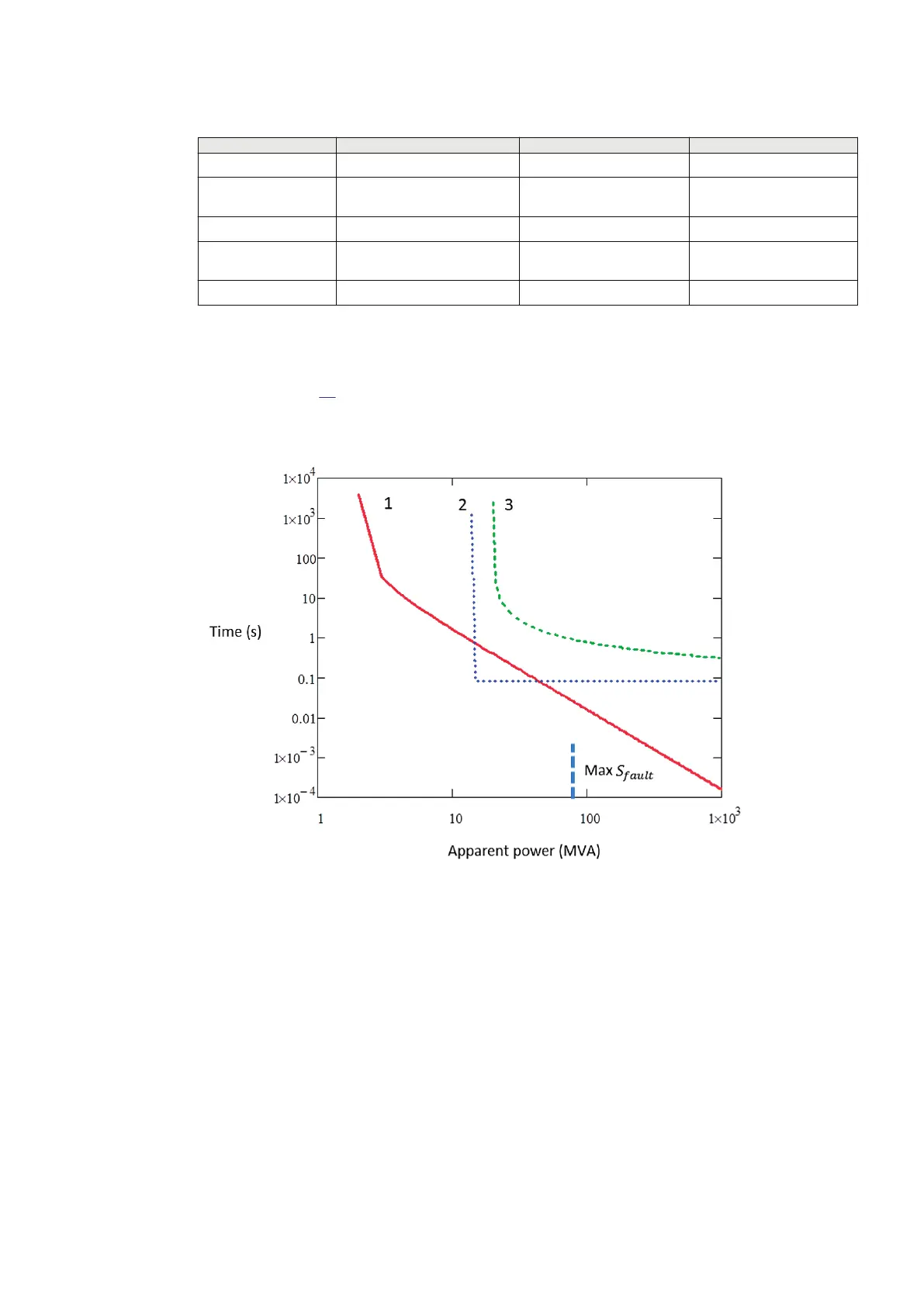
It is important to achieve a proper back-up protection. The short circuit protection on the outgoing
bays and on the LV side of the transformer are set according to a prepared selectivity chart. An
example in Figure
39 shows that the setting of the short circuit protection on the LV side is 14 MVA,
and Normal Inverse has k=0.12 to give back-up to outgoing bays' relays which are extremely inverse
and selective to remote fuses.
IEC14000047 V1 EN-US
Figure 39: Selectivity chart
1MRK505382-UEN Rev. K Section 4
Analog and binary signal transfer for line differential protection
Communication set-up, 670/650 series 39
Application Guide
© 2017 - 2023 Hitachi Energy. All rights reserved
 Loading...


