The relative angle between incremental currents at both ends of the protected line falls from the initial
90 degrees to close to 0 degrees (1.145 degrees) 4 ms after the fault occurrence. This angle is not
available as an output signal.
Internal fault is declared in 5 ms, and the harmonic block that could delay the trip is deactivated.
L4CPDIF initiates an internal trip decision in 6 ms by which time the start signal has been confirmed
3 times in succession as a special security measure. The trip command will be issued by the IED
after the trip decision is made with the added delay time form the hardware and communication.
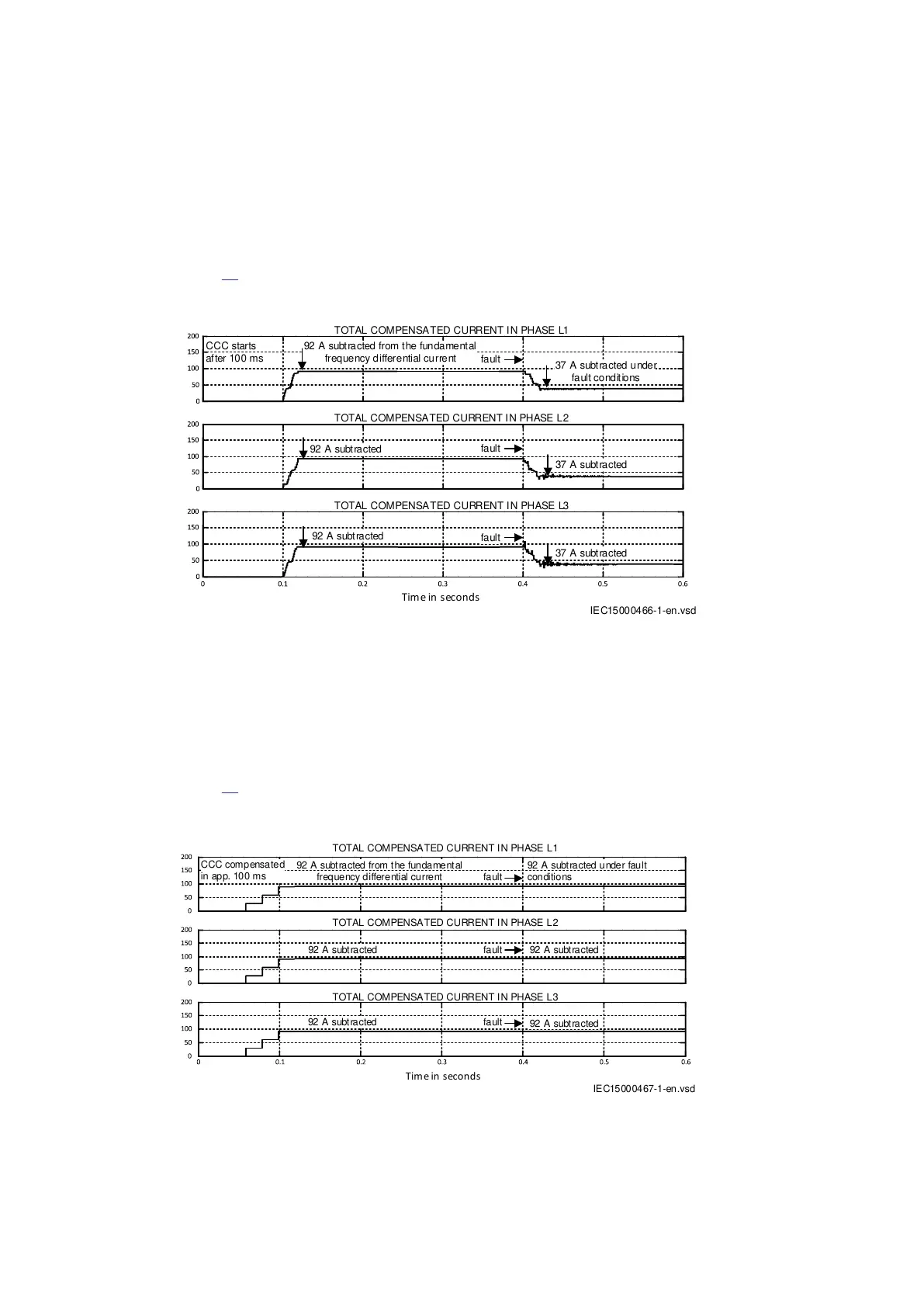
Figure
43 shows charging current compensation when the exact method is used (CCCOpMode = U
based). The charging current is subtracted from all three phases.
TOTAL COMPENSATED CURRENT IN PHASE L1
37 A subtracted under
fault conditions
92 A subtracted from the fundamental
frequency differential current
37 A subtracted
92 A subtracted
fault
fault
fault
37 A subtracted
92 A subtracted
CCC starts
after 100 ms
TOTAL COMPENSATED CURRENT IN PHASE L2
TOTAL COMPENSATED CURRENT IN PHASE L3
Tim e in seconds
IEC15000466-1-en.vsd
IEC15000466 V1 EN-US
Figure 43: Charging current compensation using the exact method
Charging current compensation starts 100 ms after simulation start when the power line was
switched on to normal load. Under normal load conditions, approximately 92 A is subtracted, which
results in all fundamental frequency differential currents being close to zero. Under fault conditions
with very low voltage at the fault and decreased voltages at both ends, the charging current is
smaller, and only 37 A is subtracted from the differential currents.
Figure
44 shows charging current compensation when the approximate method is used
(CCCOpMode = IDiff reduction). The charging current is subtracted from all three phases.
IEC15000467-1-en.vsd
fault
fault
fault
TOTAL COMPENSATED CURRENT IN PHASE L1
TOTAL COMPENSATED CURRENT IN PHASE L2
TOTAL COMPENSATED CURRENT IN PHASE L3
92 A subtracted
92 A subtracted
92 A subtracted
92 A subtracted
92 A subtracted from the fundamental
frequency differential current
92 A subtracted under fault
conditions
Tim e in seconds
CCC compensated
in app. 100 ms
IEC15000467 V1 EN-US
Figure 44: Charging current compensation using the approximate method
Section 4 1MRK505382-UEN Rev. K
Analog and binary signal transfer for line differential protection
44 Communication set-up, 670/650 series
Application Guide
© 2017 - 2023 Hitachi Energy. All rights reserved
 Loading...


