18 19
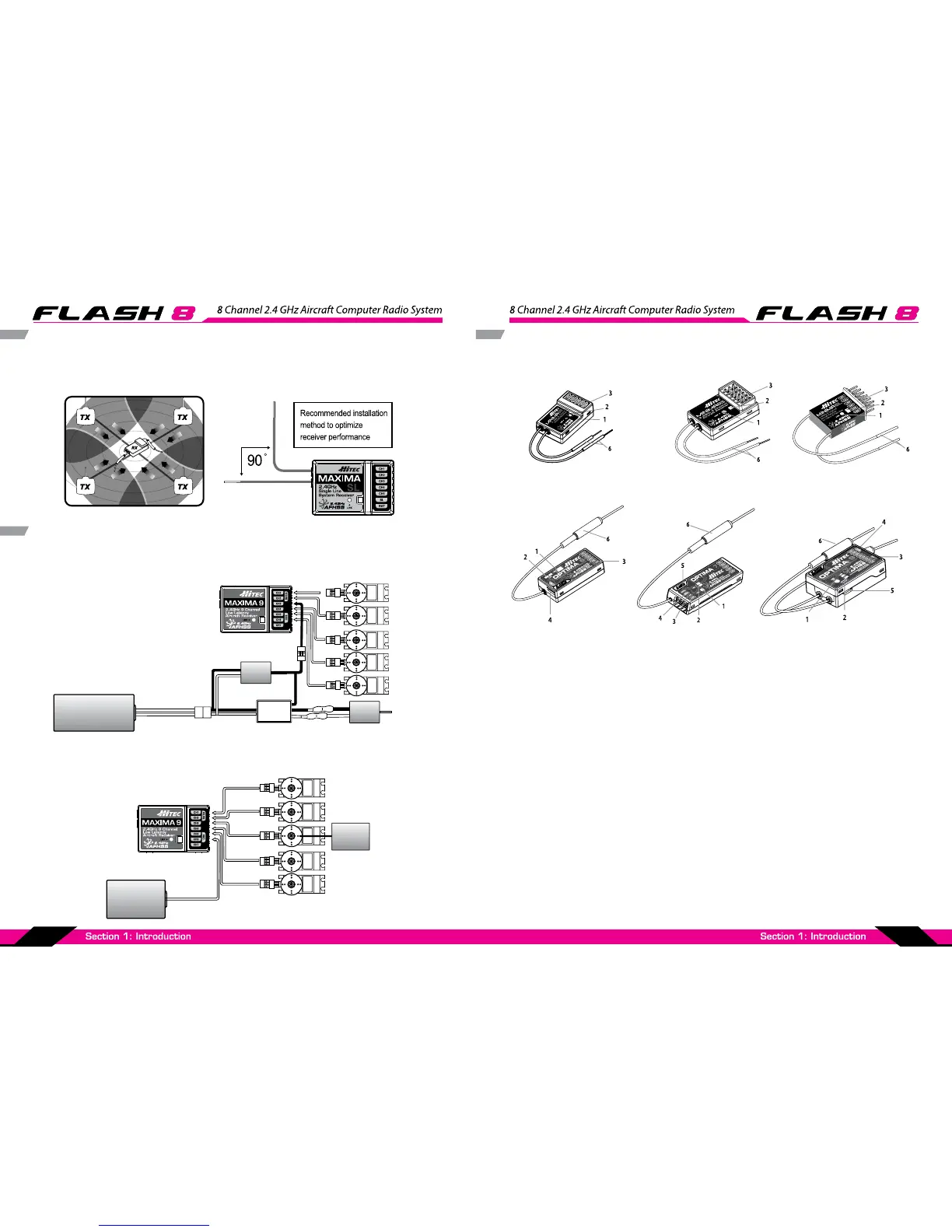
Maxima Series Receiver Antenna Installation
The Maxima receiver series antenna system was created to provide the optimum signal capture
capability. Our two antennas must be installed properly. Refer to the illustration below.
Electric powered aircraft with Electronic Speed Control
Use this method on electric planes using ESC’s providing power to the receiver and servo functions.
Maxima Series Receiver Connection Diagrams
SERVO
SERVOS ERVO SERVO
Power Battery
Motor
SERVO
BEC
ESC
Glow, gas or electric powered aircraft using a separate receiver battery supply.
Follow this connection diagram when using a regulated Li-Po, or 4.8 to 6V receiver battery.
SERVOSERVO SERVO SERVO
Receiver
Battery
SERVO
Engine
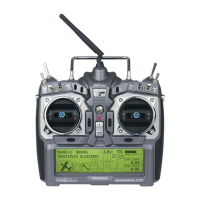
Optima and Minima Series Receiver Features
1. Function Button: Used for binding the receiver to a module or Hitec 2.4 built-in transmitters, entering
the FAIL-SAFE or Hold feature.
2. Dual LED: Status Indicator: Indicates the set-up process codes and current status of the receiver.
3. Channel Output and Battery Input Ports: The ports for battery power input and servos, gyros and
other accessories’ output ports are located at the side.
4. SPC (Supplementary Power Connection)*: Power the Optima and Minima receivers function with up
to a 35V. electric aircraft motor battery.
5. Telemetry Sensor and Data Port*: A three pin servo plug connector port is featured on the Optima 8
and Optima 9 (Optima 6 is not applicable.) Using the HPP-22 PC interface accessory, this port serves to
facilitate upgrading the device’ s software and interfacing the optional onboard sensor station.
6. BODA (Boosted Omni Directional Antenna) System*: Hitec’s exclusive 2.4GHz BODA System will show
you another way of using our 2.4GHz systems. The single Omni-directional antenna booster makes it
much easier to install the 2.4GHz antenna. Intensive tests have proven that the single BODA system
in our 6 & 7 channel systems is better than or equal to our competitor’s dual antenna systems while
our Optima 9 receiver features a dual BODA system to give the added security that larger models need.
Installation is easy and simple, insert the antenna into the supported antenna holder and stick it to the
desired spot you wish to install.
The following information contains the complete directions on how to use the Optima and Minima series
receivers (version 3.00(0). We encourage you to review this information before using these products.
MINIMA 6S MINIMA 6LMINIMA 6E & MINIMA 6T
(6T output block is on top)
OPTIMA 7
OPTIMA 9OPTIMA 6 & OPTIMA 6 LITE
(6L utilizes a soft case and exposed output block)