14
15
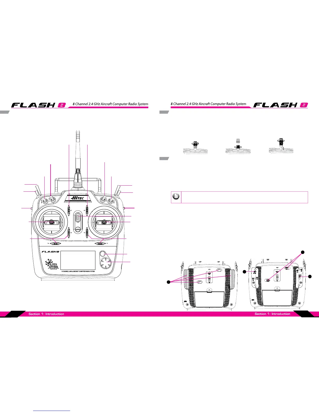
FLASH 8 Transmitter Controls
Left Slider Right Slider
Right Gimbal
J1/J2
Left Gimbal
J3/J4
Left Gimbal
Trims
Right Gimbal
Trims
Switch E
3 Position
Switch G
3 Position
Switch F
2 Position
Switch H
Momentary
Contact
Switch A
3 Position
Switch B
2 Position
Button C
3 Position
Right Digital Trim
Left Digital Trim
Switch D
3 Position
Back Button
Power Switch
Jog Dial
Scroll/Enter
Stick Length Adjustment
Stick Lever Tension Adjustment / Mode Change
Hands come in all sizes so to accommodate everyone we use a two piece stick “top” that can be adjusted
to t a wide variety of users.
Separate the top from the bottom piece and adjust the top piece to the length required.
Screw the bottom up against the top piece to “jam” lock everything into position.
Stick Lever Tension Adjustment
User may adjust the tension of the stick to t one’s own preference.
To start, please open the rubber grip on the back of the radio.
After removing the rubber grip, you may nd parts in the small hall as shon on.
With using a small allen wrench to turn the screw, you may x the tension.
Clockwise turn will tighten the tension, while counter clock wise will loosen the tension.
Change to ‘Mode 1’ Conguration
All Flash8 systems sold in US are in ‘Mode 2’ format. However, you may wish to use Flash8 in ‘mode 1’ format.
There is a menu choice for this option in the Initial Set-Up function menu described on Page 44.
After selecting ‘Mode 1’ in the Initial Set-Up Menu, you must do the following hardware set-up in order to
change the transmitter
1. Remove the four rubber grip on the back of the radio.
2. Adjust the bolt of the throttle Ratchet.
3. Loosen the hex bolt in order to create enough tension of the spring and also for neutrality of the stick.
4. Fasten until you do not feel the tension of the spring.
5. Please put the rubber grip back to its’ original place.
Please use 1.5mm allen wrench.
After adjusting the tension, please put the rubber grip back to its’ original place.
N