66 67
Ail Diff cont.
You can customize individual travel values in the “AILE” and “AIL2” elds by scrolling to those
elds and activating the sub-menus.
6. Press the back button to return to the model function menu.
Note
Elevon Mix
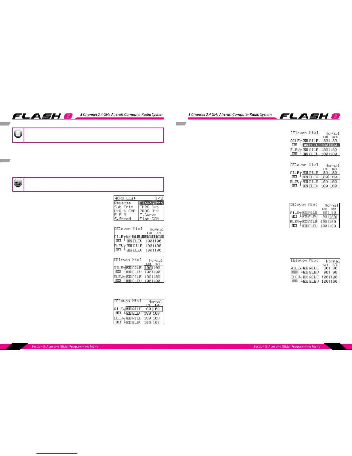
Flying wing aircraft are most often set up using elevon control surfaces. The FLASH 8 mixes the aileron
and elevator functions to provide this conguration with just one ight control surface per wing panel.
It is not necessary to access or change this menu to y an elevon-equipped aircraft. The default
values are 100% in all directions.
1. From the model menu, rotate the jog dial to highlight “Elevon
Mix” and press the jog dial once to enter the elevon mix menu.
2. Scroll to the top “AILE” eld and press the jog dial to activate
the menu.
3. Scroll to highlight the “L/U” (left/up) eld and press the jog dial
to activate the menu.
4. Rotate the jog dial to increase (clockwise) or decrease
(counter-clockwise) the desired endpoint for the servo
attached to the “AILE” receiver slot. This value regards the servo
travel when a left roll command is given. Press the jog dial to
conrm your input.
5. Scroll to highlight the “R/D” (right/down) eld and press the
jog dial to activate the menu.
6. Rotate the jog dial to increase (clockwise) or decrease
(counter-clockwise) the desired servo endpoint when a right
roll command is given. Press the jog dial to conrm your input.
TipTip
Tip
Elevon Mix cont.
11. Scroll to highlight the “R/D” (right/down) eld and press the
jog dial to activate the menu.
12. Rotate the jog dial to increase (clockwise) or decrease
(counter-clockwise) the desired servo endpoint when a right
roll command is given. Press the jog dial to conrm your input.
13. Press the back button the to return to the elevon mix menu.
14. Repeat steps 2-13 using the lower “AILE” and “ELEV” elds to set the servo endpoints when pitch
(elevator) commands are given.
7. Press the back button the return to the elevon mix menu.
8. Scroll to the top “ELEV” eld and press the jog dial to activate
the menu.
9. Scroll to highlight the “L/U” (left/up) eld and press the jog dial
to activate the menu.
10. Rotate the jog dial to increase (clockwise) or decrease
(counter-clockwise) the desired endpoint for the servo
attached to the “ELEV” receiver slot. This value regards the
servo travel when a left roll command is given. Press the jog
dial to conrm your input.
15. If aileron or elevator functions operate in the incorrect
direction, highlight the direction eld (“nor”) under the
function name and press the jog dial to activate the menu.
16. Scroll to select “rev” and press the jog dial to conrm your
selection. Verify that the control surfaces now move in the
correct direction.
18. Push the Back button twice to return to the model function menu.