EasyManua.ls Logo

Holley EFI - Optional I;O Connector Details; I;O Connector Pinout and Functions

Holley EFI
50 pages
Print Icon
To Next Page IconTo Next Page
To Previous Page IconTo Previous Page
Loading...
45
Figure 4. Flip door down
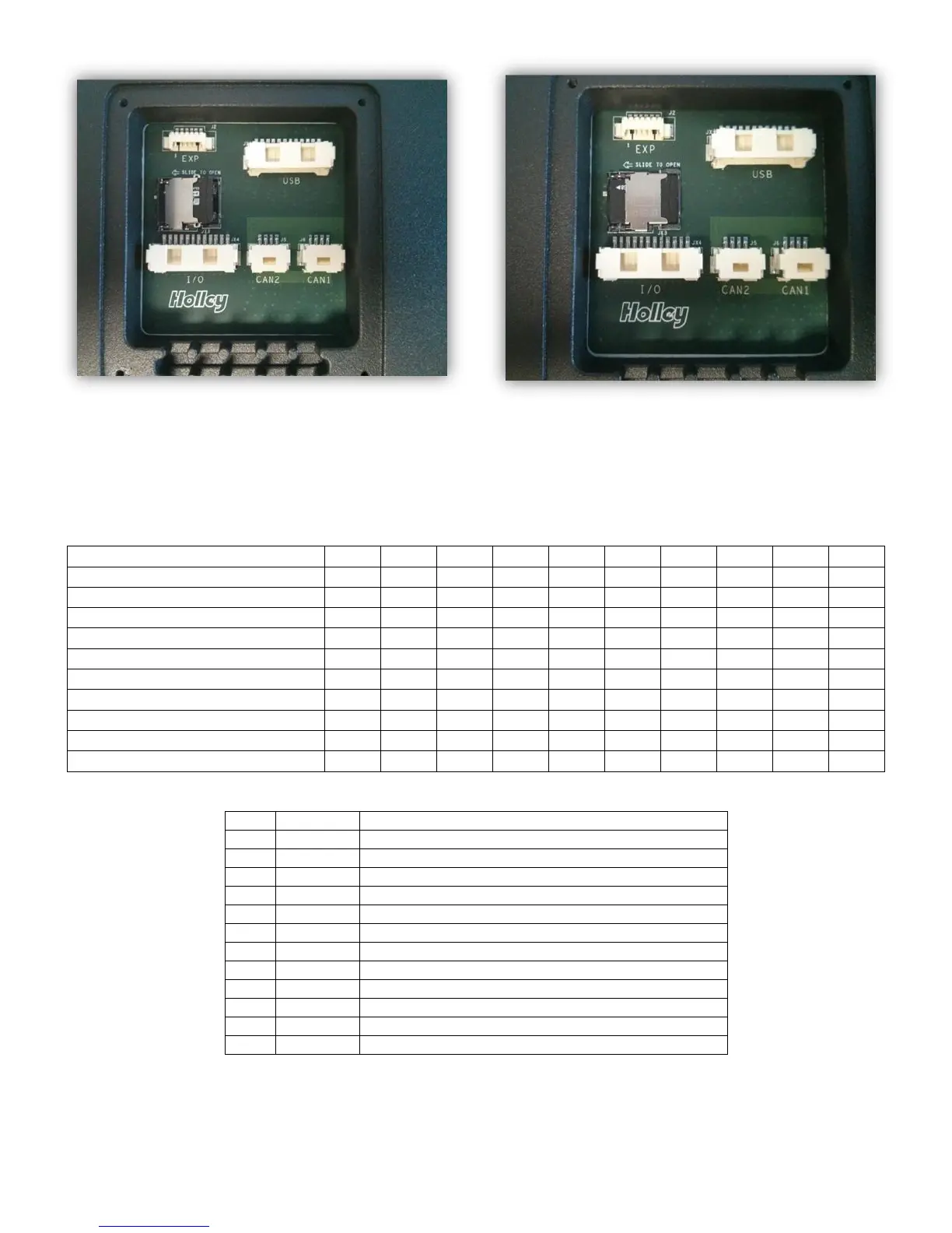
Figure 5. Slide door to the right to lock
Optional I/O Connector
The internal I/O connector can be used for stand-alone applications or as additional inputs and outputs. An
optional I/O adapter is available as part number 558-432, 558-433 or 558-434.
IO1
IO2
IO3
IO4
IO5
IO6
IO7
IO8
IO9
IO10
SSR GND switched output (2A)
Y
Y
5V Input
Y
Y
Y
Y
Y
Switch to GND input
Y
Y
Y
Y
Y
Y
Y
Switch to +12V input
Y
Y
Y
Y
Y
Y
Y
RPM Input
Y
Y
Speed Input
Y
Y
Oil Pressure (5V)
Y
Resistive Sensor to GND
Y
Y
Y
CTS / MAT Sensor to GND
Y
Y
Y
Fuel sender input
Y
I/O Connector Supported Functions
Pin
Function
Sample use
1
5V EXC
5V excitation output for sensors
2
IO1
Left turn input or General I/O
3
IO2
Right turn input or General I/O
4
IO3
Digital Engine RPM input or General I/O
5
IO4
Digital Speed Input or General I/O
6
IO5
High beam input
7
IO6
Brake input
8
IO7
Oil pressure input
9
IO8
Oil temperature sender input, built-in pullup
10
IO9
Coolant temperature sender input, built-in pullup
11
IO10
Fuel sender input, built-in pullup
12
GND
Ground reference
I/O Connector Pinout

Related product manuals