Fire Alarm Control Panel Compact
6 FB 798238.GB0 / 10.14
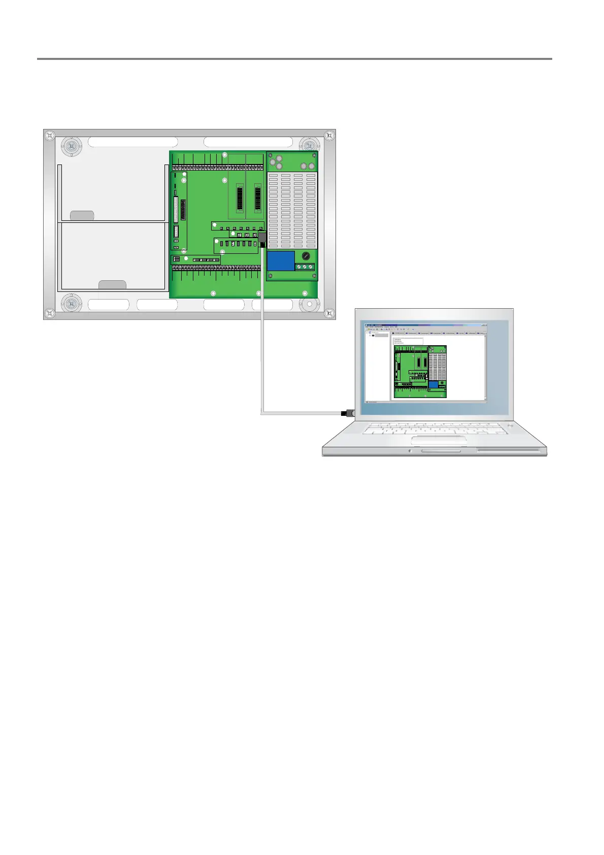
2.2 Connection between the FACP and service PC
The service PC and the FACP are connected via USB for configuring / programming the FACP Compact.
NL1PE
BATT
+
-
TEMP
HOUSING
BAT T SERVICE RE SET
EA RTH ALA RM
THRES
SYSERR
OUT_1
OUT_3
OUT_4
R_ 4
FIRE PROT. ZONE ZONE/E SSERBUS
GND
IN_3
- 1 + - 2 + - 3 + - 4 + - 5 + - 6 + - 7 + - 8 +
GND +24 V
GND
+OUT_1
RS 485
AB
SLOT1 SLOT2
1234 56 78
SYSERR
SYSERR
AL A RM
BOOT OP US B
EXTENSION BOARD
TO HMIAUX
PC
R_2 R_3 R_4 R_5
EXT STD
NC NO NC NO NC NO NC NO
FIRE
PROT
9 1011121314 1516 17181920212223 2425 2627 2829 3031
IN_ 1
- OUT _2
+OUT_2
IN_ 2
GND
- OUT _3
+OUT_3
- OUT _4
+OUT_4
FE 123456 123456
1 2 3 4 5 6 7 8 9 10 11 12 13 14 15 16 17 18 19 20 21 22 23 24 25 26 27 28 29 30 31
R_2 R_3 R_4 R_5R_ 1 R_ 1
GND
IN_4
DI S
42V
A+ A- B+ B-
LOOP
FAULT
LOOP
COM M
X1
X2
1
2
3
4
6
5
NL1PE
BAT T
+-
TEMPHOUSING
BATT SERVICE RESET
EARTH ALARM
THRES
SYSERR
OUT_1
OUT_3
OUT_4
R_4
FIR E PROT.
ZO NE ZO NE /E S S E RBU S
GND
IN_ 3
- 1 + - 2 + - 3 + - 4 + - 5 + - 6 + - 7 + - 8 +
GND + 24 V
GND
+OUT_1
RS485
AB
SLOT1 SLOT2
123 456 78
SYSERR
SYSERR
ALARM B OOT OP USB
EXT ENSIO N B OA RD
TO HMIAUX
PC
R_2 R_3 R_4 R_5
EXT STD
NC NONC NO NC NO NC NO
FIRE
PROT
9 1011 12 1314 15 16 1718 19 20 2122 23 24 25 26 27 28 293 0 31
IN_1
- OUT_2
+OUT_2
IN_2
GND
- OUT_3
+OUT_3
- OUT_4
+OUT_4
FE123456123456
1 2 3 4 5 6 7 8 9 10 1112 13 1415 16 17 1819 20 21 22 23 24 25 262 7 28 29 3031
R_2 R_3 R_ 4 R_ 5
R_1 R_1
GND
IN_ 4
DIS
42V
A+ A- B+ B-
LOOP
FAULT
LOOP
COMM
X1
X2
1
2
3
4
6
5
ES Lin e Ze ntra l
Fig. 3: Service PC
FACP at USB port on the 1
st
control module
The communication between the service PC and the fire alarm control panel Compact is shown in the lower left
corner of the programming interface tools 8000 with the green symbols for data exchange and USB connection.

 Loading...