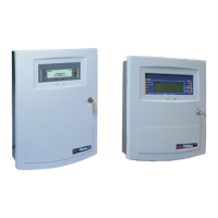
Fire Alarm Control Panel LT-32 / LT-159
20 M-168.1-SERIE-LT-EN / 08.2022
QUALITY OF CABLE
It is vitally important that good quality cable is used and that correct installation techniques are followed. In general, the following cable installation requirements
must be met:
1. All cable sections must be circular to allow effective cable clamping using the cable glands.
2. The cable must be screened (sheathed) to provide protection against Radio Frequency Interference (RFI) and the screen must be connected to earth at the
control panel (earthing points are provided on the inside enclosure top side).
3. The cable screen must be continuous throughout the loop. Please connect the screen to a ground/earth point.
LOOP CABLE LENGTH
A loop circuit consists of devices such as detectors and modules. The length of a loop circuit cable used can be significantly affected by the loading of the device on
a loop circuit. The length can be up to 500 m and is determined by cable type and loop loading.
RECOMMENDED CABLES
Type of cable: 2 conductors (for their section refer to the table below)
• Twisted narrow pitch (5 / 10 cm)
• Shielded pair cable
• Max. admitted capacity: 0,5 µF
• Max. resistance depending on the current loop in alarm (number of sounder / strobes activated simultaneously): 10 Ohm
CABLE SECTIONS
The proposed sections are referred to the total length of the line (in case of Class A loop and therefore when the loop is closed, it is considered the loop length)
which, however, must not be longer than 500 m and the total resistance of the line must be lower than 10 Ohm.
2
2
 Loading...