Fire Alarm Control Panel LT-32 / LT-159
22 M-168.1-SERIE-LT-EN / 08.2022
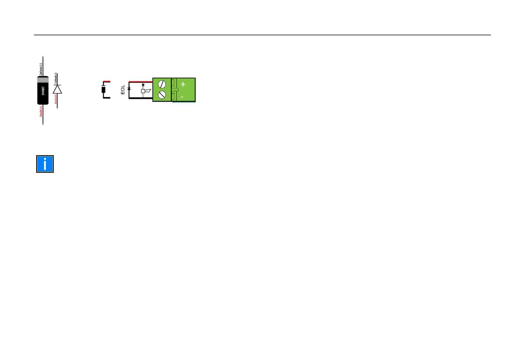
Sounder circuit
End of line diode cathode marker on positive terminal.
Fig. 15: Example of sounder circuit
Connections on 7 and 8 differs between LT-32 and LT-159 FACP.
FAULT/ALARM RELAY CONFIGURATION
The fault/alarm relay can be configured as normally open or normally closed, using the Jumper J16 for the Fault Relay and J18 for the Alarm relay.
LOOP CONNECTION
LT-32 requires two wires: (+) positive and (-) negative of the LOOP terminals.
LT-159 requires a closed loop: connectors J12 and J11 are used to connect side “A” and side “B” of the loop.
SOUNDER CONNECTION
LT-32 is equipped with two sounder outputs: OUT 1 and OUT 2 balanced with diodes provided with the panel.
LT-159 is equipped with one sounder output: OUT 1balanced with a diode provided with the panel.
POWER CONNECTION
LT-32 / LT-159 have a PSIN connector to wire the provided AC power supply.
For all the connections, please refer to the below figures.

 Loading...