52 NFS2-3030 Programming Manual — P/N 52545:K1 03/20/2012
Program Point Program
Module Point Programming (Monitor Module)
Pressing the MORE soft key at the Module Point Programming screen will display this screen if the
module type was monitor.
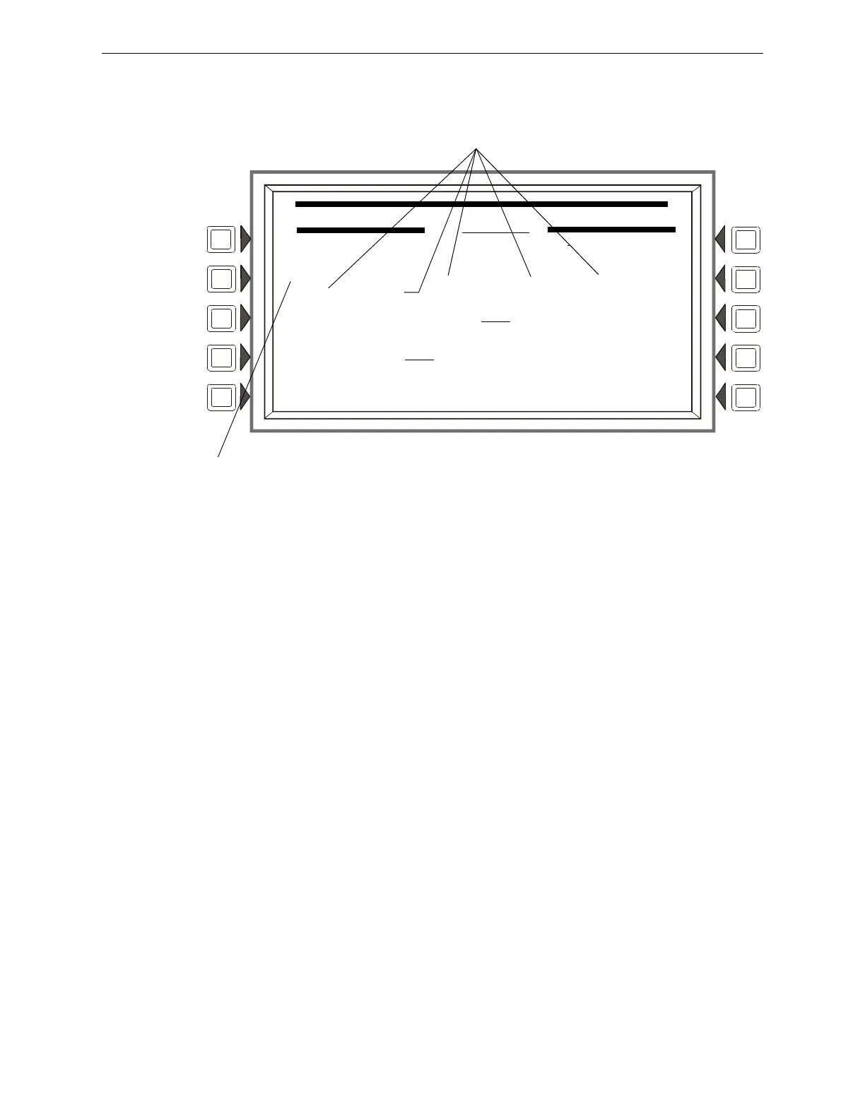
Figure 3.41 Module Point Programming Screen 2 (Monitor)
Soft Keys
CUSTOM ACTION MESSAGE: Disp
lays the custom action message number (a value of one
through 100). The default value is 0 (no message). Press this soft key to progress to the Custom
Action Message screen (shown in Figure 3.35) to view the message or to choose a different
message for viewing when this point activates. To create
a new cus
tom action message, refer to
Section 3.3.5, “Custom Action Message”, on page 41.
ZONE MAP: Disp
lays the zones mapped to this point. During initial programming, zone map
position one for each monitor module is set to Z0YY, where YY represents the loop number where
the module resides. In Figure 3.41 above, zone position one has a value of Z003 (YY = 03). The
module in the example resides on loop 3.
To add or delete zones, press this soft key to proceed to the
Module Zone Map screen. Refer
to
“Zone Map” on page 45 for an illustration and explanation of the Detector Zone Map screen. The
Module Zone Map screen is the same except that Module replaces Detector in the title and the
module address appears instea
d of the detector address. Up to ten general, releasing or special
zones may be mapped to a monitor module: none of the zone map positions are fixed. Positions 1
and 3 - 7 have additional functionality.
Position 1 - This position is checked when a group zone
disable command
is issued. If the zone
number in the group zone disable command matches the zone number in the first position of
the zone map, the module point will be disabled.
Positions 3 - 7 - For the FMM-4-20 module only.
These positions are assigned to FMM-4-20
threshold levels 1 - 5 respectively. (Threshold levels are user-programmed. Refer to “FMM-4-
20 Monitor Module Programming” on page 53.) Each will activate only if the device is
currently at that threshold level. Once
the
device leaves that threshold level, the zone in its
corresponding CBE position will remain active or deactivate according to whether its threshold
is programmed for latching or tracking.
ALARM VERIFICATION: Press
this key to determine participation in Alarm Verification.
Choosing Yes will set the device participation to the value entered at the Panel Timers screen
(Figure 3.14). The only module type that can participate in alarm verification is the FZM-1.
MODULE POINT PROGRAMMING
L03M123
CUSTOM ACTION MESSAGE:020
ZONE MAP:
Z003 , Z104 , Z105 , Z106 , Z107
Z110 , Z114 , Z115 , Z116 , Z117
ALARM VERIFICATION: OFF MORE
LOCAL MODE: OFF ACCEPT
4-20 DEVICE SETUP BACK
Zone Map Position 1 - Use for group zone disable participation.
This menu selection will appear when 4-20MA has been entered as the module’s Type Code Label.
FMM-4-20 only - Positions 3 - 7 in the zone map are
automatically assigned to thresholds 1 - 5 respectively.
 Loading...


