14 MODBUS-GW Installation and Operation Manual — P/N LS10015-000NF-E:C2 4/30/2019
Section 2 Installation
2.1 Required Equipment
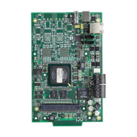
2.1.1 MODBUS-GW Assembly:
The following components are shipped with the MODBUS-GW:
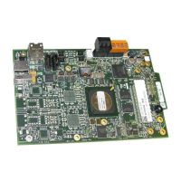
• MODBUS-GW Printed Circuit Board
• Surge Suppressor (P/N PNET-1)
• NUP-to-NUP Cable (P/N 75577) - Used to connect the MODBUS-GW board to an NCM-W or NCM-F board or supported
panel.
• Wire Leads-to-NUP Cable (P/N 75583) - Used to connect 24V power from the MODBUS-GW board to an NCM-W or NCM-F
board.
• USB Cable (P/N 75665) - Used to connect the MODBUS-GW board to an HS-NCM board:
2.1.2 Network Components:
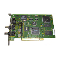
• High-speed Network Communication Module (HS-NCM) - Used to facilitate network communication between the
MODBUS-GW and a high-speed NFN network (sold separately).
OR
• Network Communication Module (NCM) - Used to facilitate network communication between the MODBUS-GW and an NFN
network (sold separately).
OR
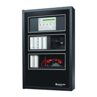
• Compatible FACP with NUP port.
2.1.3 Customer Supplied Equipment:
• Computer - Used to run a web browser to configure the MODBUS-GW. Refer to 1.4, "Required Software" for recommended
browsers.
• Ethernet Patch Cable - Used for connecting to the Local Area Network (LAN).
–HS-NCM-W –HS-NCM-MF
–HS-NCM-WMF –HS-NCM-SF
– HS-NCM-WSF – HS-NCM-MFSF
 Loading...

