MODBUS-GW Installation and Operation Manual — P/N LS10015-000NF-E:C2 4/30/2019 17
Connections Installation
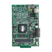
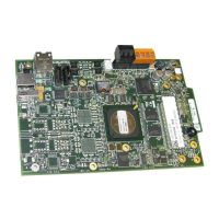
Figure 2.6 MODBUS-GW LEDs
Table 2.2 LED Definitions
Reference
Designator
Label Description
D1 ACTIVE Active/Lit indicates that WinCE is running.
D2 NUPA RX Blinks when data is received on the NUP A port (J4).
D3 PROGRAM Not Used
D4 NUPB RX Not Used
D7 USB B Active/Lit indicates a device is connected to the USB B port (J1).
D8 NUPA TX Blinks when data is sent on the NUP A port (J4).
D9 USB A Active/Lit indicates a device is connected to the USB A port (J2).
D10 NUPB TX Not Used
D11 DATA Blinks to indicate data transmission to or from the Ethernet port (J3).
D12 LINK Active/Lit indicates an Ethernet connection.
D22 WDT FAIL Active/Lit indicates the system has undergone a reset due to a Watchdog
circuit activating.
D22
D2
D4
D8
D10
D1
D3
D7
D9
D11
D12
(J3)
(J4)
(J1)
(J2)
(J5)
(TB1)
(TB2)
LEDs
(See Table Below)
 Loading...

