MODBUS-GW Installation and Operation Manual — P/N LS10015-000NF-E:C2 4/30/2019 37
Bell Circuits Device Type Holding Registers Register Mapping
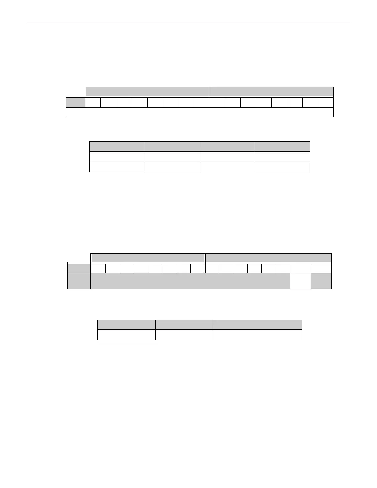
5.6 Bell Circuits Device Type Holding Registers
Each bell circuits device type holding register address consists of two bytes (upper and lower) as defined in Table 5.11 representing two
bell circuits as shown in Table 5.12.
5.7 Panel Status Holding Register
The panel status holding register is divided into an upper and lower byte as described below and in Table 5.13 representing one register
address as shown in Table 5.14.
• Silence: The fire alarm control panel is silenced when this bit is set to 1.
• Reset: Not used.
Table 5.11 Bell Circuits Device Type Holding Register Bit Definitions
Upper Byte Lower Byte
Bit No.
151413121110987 6543210
Device Types (see Appendix D)
Table 5.12 Bell Circuit Device Type Holding Register Addresses
Start Address End Address Device Address Device Address
49410 49410 Bell Circuit 2 Bell Circuit 1
49411 49411 Bell Circuit 4 Bell Circuit 3
Table 5.13 Panel Status Holding Register Bit Definitions
Upper Byte Lower Byte
Bit No. 15 14 13 12 11 10 9 8 7 6 5 4 3 2 1 0
Bit
Name
Not Used Silence Reset
Table 5.14 Panel Status Holding Register Addresses
Start Address End Address Description
49500 49500 Panel Status Holding Register

 Loading...


