38 MODBUS-GW Installation and Operation Manual — P/N LS10015-000NF-E:C2 4/30/2019
Register Mapping Analog Values Input Registers
5.8 Analog Values Input Registers
Analog values listed in Table 5.15 are only available for 4–20 mA modules. Refer to 4.4, "Analog Values and Trending" for details
regarding analog values.
5.9 Panel and System Troubles Input Registers
Sixty-four 16-bit registers are reserved for panel troubles and one register is assigned as an overall panel trouble indicator as shown in
Table 5.16.
A single bit is reserved for each trouble in the system. The assignment of bits to trouble codes is shown in Appendix E, “System
Troubles”.
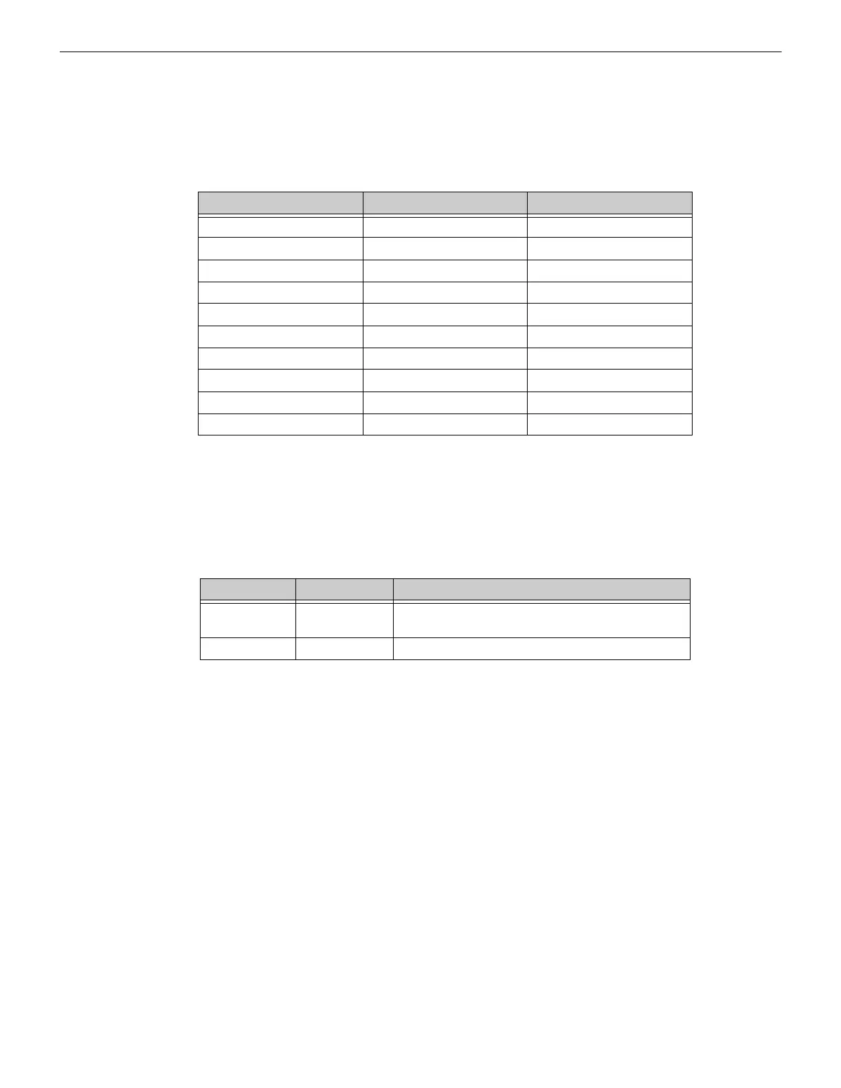
Table 5.15 Input Register Analog Values
Start Address End Address Analog Value (16 bits)
30001 30200 L1M1–L1M159
30201 30400 L2M1–L2M159
30401 30600 L3M1–L3M159
30601 30800 L4M1–L4M159
30801 31000 L5M1–L5M159
31001 31200 L6M1–L6M159
31201 31400 L7M1–L7M159
31401 31600 L8M1–L8M159
31601 31800 L9M1–L9M159
31801 32000 L10M1–L10M159
Table 5.16 Panel and System Troubles Input Register Addresses
Start Address End Address Description
35000 35000 Panel Trouble Summary
(Total number of Trouble bits set for the node)
35001 35064 Panel Troubles

 Loading...


