36 MODBUS-GW Installation and Operation Manual — P/N LS10015-000NF-E:C2 4/30/2019
Register Mapping Bell Circuits Status Holding Registers
5.5 Bell Circuits Status Holding Registers
NFS2-640 and NFS-320 Only
Each of the bell circuits status holding registers are divided into an upper and lower byte as described below and in Table 5.9.
• Upper Byte: The upper byte contains general status information about the bell circuit.
• Lower Byte: The lower byte is primarily used when bit 11 in the upper byte is a ‘1’ (or active). When bit 11 is a ‘1’, refer to
Appendix C, “MODBUS-GW Active Event Types” for detailed information about the active bell circuit. The lower byte will be
all 0’s if the bell circuit is not in an active state.
Specifically, the lower byte contains the actual active event for this bell circuit. An active state is defined in this gateway as any
Fire, Security, Critical Process, Medical, Mass Notification, or Supervisory alarm state. If the bell circuit is not present in the
panel programming, all bits in the lower byte will contain a ‘1’ or the value ‘FFH’.
The holding register address and the bell circuit contained in the address is detailed in Table 5.10.
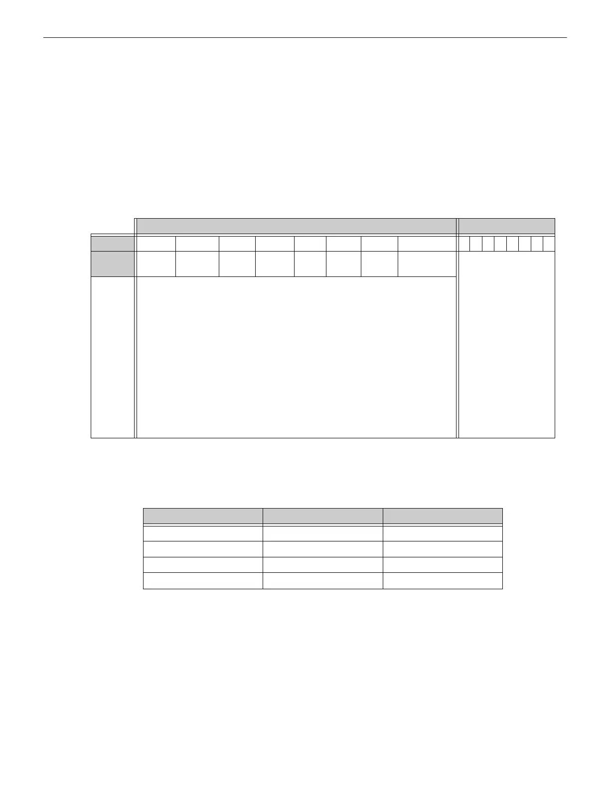
Table 5.9 Zones/Panel Circuits Holding Register Bit Definitions
Upper Byte
Lower Byte
Bit No. 15 14 13 12 11 10 9 8 76543210
Bit Name Ack
Block
Prealarm Trouble InActive Active Enable Disable Ack Fire Alarm Active Event Type
(When Bit 11 is set to 1,
see Appendix C.)
When individual upper byte bits are set to 1, the following definitions apply:
• Ack Block (Bit 15): All events on this bell circuit, other than fire alarm, are
acknowledged.
• Prealarm (Bit 14): The bell circuit is in a prealarm state.
• Trouble (Bit 13): The bell circuit is in a trouble state.
• InActive (Bit 12): The bell circuit is not active.
• Active (Bit 11): The bell circuit is active and there will be an active event type in the
lower byte.
• Enable (Bit 10): The bell circuit is enabled.
• Disable (Bit 9): The bell circuit is disabled.
• Ack Fire Alarm (Bit 8): The fire alarm on this bell circuit is acknowledged.
Table 5.10 Bell Circuit Holding Register Addresses
Start Address End Address Device Address
49400 49400 Bell Circuit 1
49401 49401 Bell Circuit 2
49402 49402 Bell Circuit 3
49403 49403 Bell Circuit 4

 Loading...


