20 MODBUS-GW Installation and Operation Manual — P/N LS10015-000NF-E:C2 4/30/2019
Installation Connections
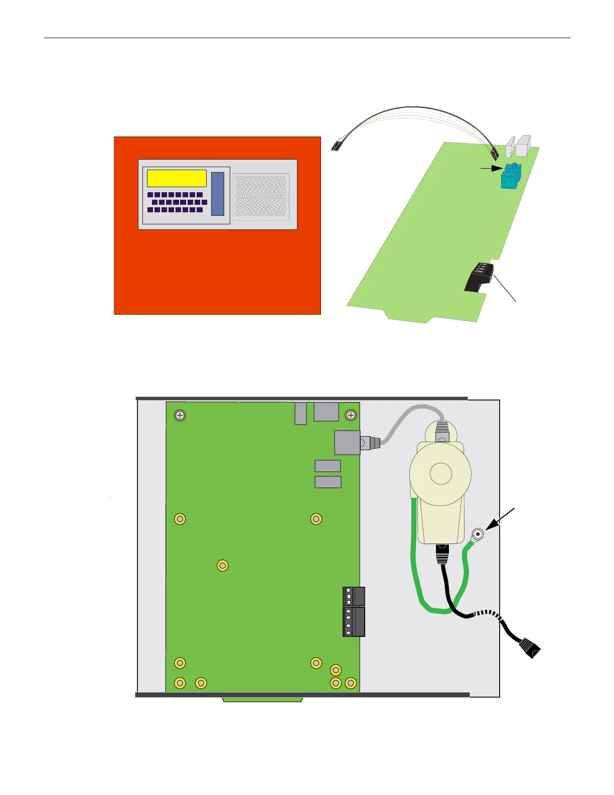
2.3.4 Connecting to a Fire Alarm Control Panel (FACP)
Figure 2.9 Connecting to an FACP
2.3.5 Connecting to the PNET-1 Surge Suppressor
Figure 2.10 Connecting to the PNET-1
FACP
From FACP
NUP Connector
NUP Cable Provides Both
Power and Communication
To NUP “A”
(J4) only
Not Used
MODBUS-GW
Panel is shown for illustrative purposes only. The
MODBUS-GW is mounted within the FACP cabinet and
connected with the NUP connection located on the
FACP.

 Loading...


