46 NFS2-640/E Programming Manual — P/N 52742:L2 7/17/14
Programming Basic Program
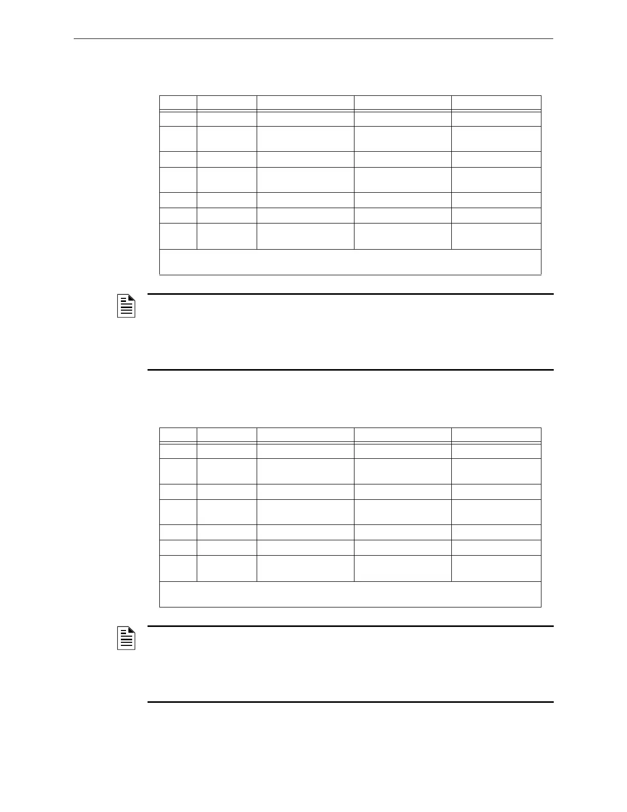
ACS Selection Group V (SLC #1, Detectors 79-100):
ACS Selection Group W (SLC #2, Detectors 79-100):
Table 2.33 ACS Group V
Point Type Red LED Yellow LED Switch Function*
1 Input Detector 079 Alarm Detector 079 Trouble Not Used
2 Input Detector 079 Trouble
Maintenance Urgent
Detector 079 Trouble
Maintenance Alert
Not Used
3 Input Detector 080 Alarm Detector 080 Trouble Not Used
4 Input Detector 080 Trouble
Maintenance Urgent
Detector 080 Trouble
Maintenance Alert
Not Used
to to (see note 1) to (see note 1)
63 Input Detector 100 Alarm Detector 100 Trouble Not Used
64 Input Detector 100 Trouble
Maintenance Urgent
Detector 100 Trouble
Maintenance Alert
Not Used
* Pressing the switch button when the Switch Function is “Not Used” will cause the associated LED to
stop blinking. This is a local acknowledgement at the annunciator only: no message is sent to the panel.
NOTE:
1. Point number to Detector number relationship is sequential in groups of 2. Since each detector
occupies 2 points, to determine the Point to Detector relationship, start with detector 79 and count
by 2 starting from point 1.
2. This group is only available when UDACT setting is programmed as option 2 and will
automatically be assigned to ACS address 30.
Table 2.34 ACS Group W
Point Type Red LED Yellow LED Switch Function*
1 Input Detector 079 Alarm Detector 079 Trouble Not Used
2 Input Detector 079 Trouble
Maintenance Urgent
Detector 079 Trouble
Maintenance Alert
Not Used
3 Input Detector 080 Alarm Detector 080 Trouble Not Used
4 Input Detector 080 Trouble
Maintenance Urgent
Detector 080 Trouble
Maintenance Alert
Not Used
to to (see note 1) to (see note 1)
63 Input Detector 100 Alarm Detector 100 Trouble Not Used
64 Input Detector 100 Trouble
Maintenance Urgent
Detector 100 Trouble
Maintenance Alert
Not Used
* Pressing the switch button when the Switch Function is “Not Used” will cause the associated LED to
stop blinking. This is a local acknowledgement at the annunciator only: no message is sent to the panel.
NOTE:
1. Point number to Detector number relationship is sequential in groups of 2. Since each detector
occupies 2 points, to determine the Point to Detector relationship, start with detector 79 and count
by 2 starting from point 1.
2. This group is only available when UDACT setting is programmed as option 2 and will
automatically be assigned to ACS address 31.
 Loading...


