32 Chapter 6 Electrical Installation
Searchline Excel™ Plus / Searchline Excel™ Edge – Technical Manual
6.1.1.1Receiver Internal Battery Cell
A primary cell featuring an expected operating life of 10 years is fitted internally. This is not accessible and replacement
must only be conducted by an authorized service centre.
6.1.2Receiver 420 mA Current Loop
The receiver provides a 420 mA current loop with HART Communication which can be user configured as a Sink, Source
(3Wire) or Isolated (4Wire) electrical interface, based on installation requirements.
Depending on configuration, the 420 mA current loop output can provide:
• discrete indication of operating modes (Normal operation, Pre-alarm, Alarm) and special states (Fault, Warning, Inhibit,
Over-range)
• proportional output to gas concentration and a discrete indication of special states (Fault, Warning, Inhibit,
Over-range).
Searchline Excel Plus & Searchline Excel Edge features HART communications to provide access to the receiver from
a control system or handheld device for the purpose of configuration and to provide status and diagnostic information.
The total load resistance for the 420 mA current loop shall be less than 600 Ω, including the resistance of the 420 mA
cable and input impedance of the equipment to be connected. To ensure reliable HART communications, the minimum loop
resistance is 250 Ω. If HART communication is not required, the minimum loop resistance is 100 Ω.
If the 420 mA current loop is not used, a jumper must be connected between 420 mA+ (terminal 5) and 24V DC+
(terminal 8) and a load resistor must be connected between 420 mA (terminal 6) and 0V DC (terminal 9).
It is recommended to use a 470 Ohm, 1/4 W resistor (250 to 400 Ω if HART is required). With the 420 mA current loop
configured this way the HART facility can still be used with a HART handheld unit using terminals 20 and 21 inside
the wiring compartment. A HART DTM is available for Searchline Excel Plus and Searchline Excel Edge.
The maximum permissible mA loop voltage is 32 VDC and the maximum current is 22 mA.
6.1.3Relays
The receiver features 3 SPDT relay outputs for alarm and fault indication. Relay 1 is for alarm level 1, relay 2 is for alarm
level 2, and relay 3 indicates faults. The fault relay is normally energized and when energized indicates proper operation
(no faults present).
In the event of power failure or fault, the COMNO connection will open. If required, the fault relay may be configured as
normally de-energized.
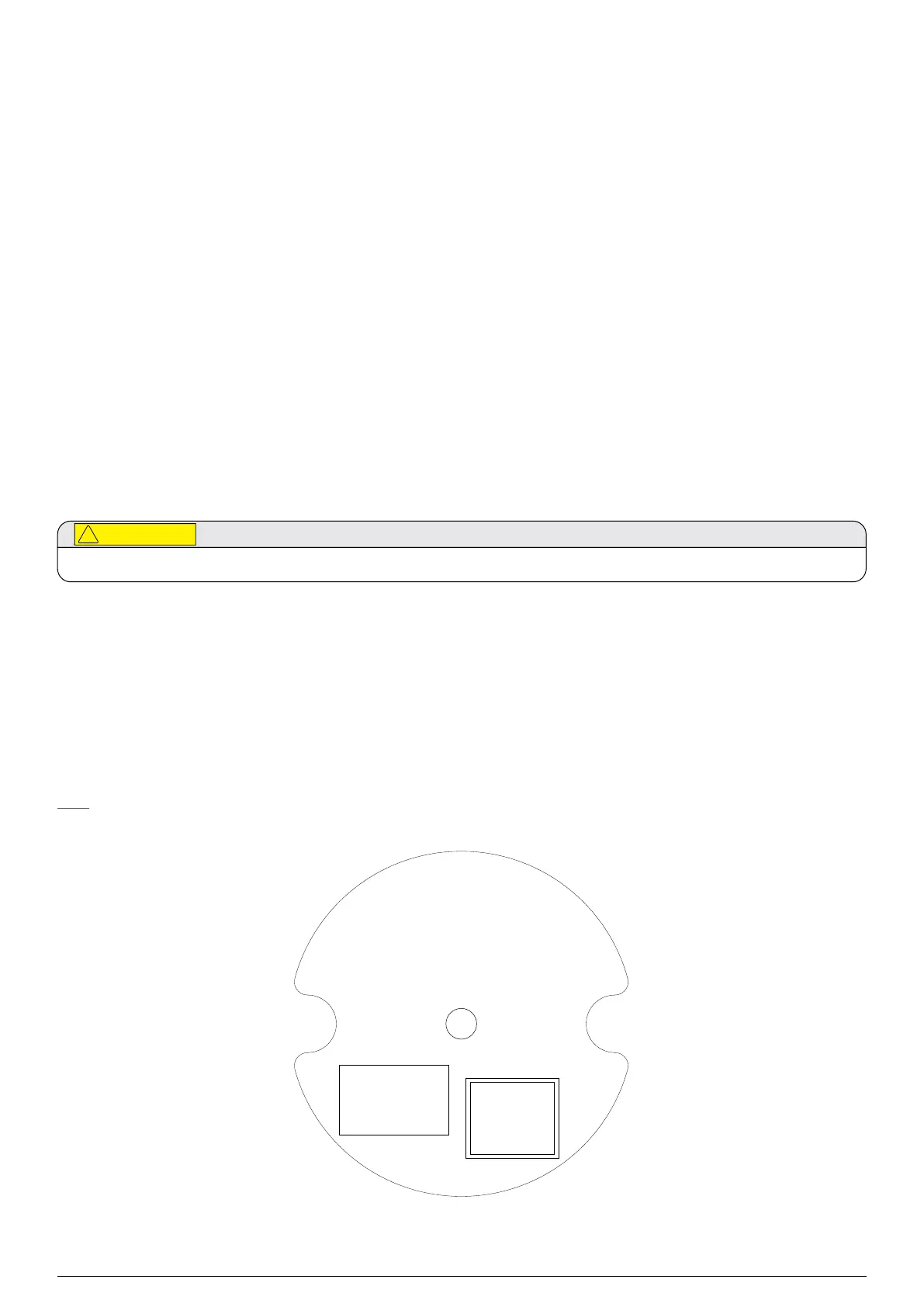
6.2Receiver Connections / Wiring Diagram
Note
24 V pins number 7 & 8 and 0 V pins number 9 & 10 are internally linked.
Ø=78 mm
NOTES:
1.MATERIAL:
LABEL:2331D0238
INKRIBBON:BRADYR6000THERMALTRANSFERPRINTED-BLACK.
2.THISPRODUCTMUSTBERoHSCOMPLIANT
3.VALUESSHOWNONARETYPICALANDAREFORINFORMATIONPURPOSESONLY.PRODUCTDATAISENTEREDBYTHEPRODUCTIONCONFIGURATIONSYSTEM
2017D0250
THISDOCUMENTHASBEENGENERATEDUSINGINDESIGN
ANDMUSTONLYBEUPDATEDBYINDESIGN
FINISH
N/A
MATERIAL
SEENOTE1
SCALE
1:1
1 ISSUE
14/05/20
DATE
A05398
CHANGE
KSM
ACTIONEDBY
DRAWNK.SMRCEK DATE19-Feb-20
TITLE
SEARCHLINEEXCELRx
INNERREARCOVERLABEL
2017D0250
SHT.1
OF1
©2020LIFESAFETYDISTRIBUTION
GmbH.
ALLRIGHTSRESERVED.
THISDOCUMENTCONTAINSPROPRIETARY
INFORMATIONOFLIFESAFETY
DISTRIBUTIONGmbHANDITSAFFILIATED
COMPANIESANDISPROTECTEDBY
COPYRIGHTANDOTHERINTERNATIONAL
LAWS.REPRODUCTIONORIMPROPER
USEWITHOUTSPECIFICAUTHORIZATION
OFLIFESAFETYDISTRIBUTIONGmbHIS
STRICTLYFORBIDDEN.
TOLERANCESTOBEASSPECIFIED
BELOWUNLESSOTHERWISESTATED.
DIMS.2DP±0.1mm
1DP±0.25mm
NONE±0.4mm
ANGULAR±1/2°
HOLESØ0to8
+0.08
-0.0
Ø8to14
+0.1
-0.0
Ø14to25
+0.12
-0.0
UNLESSOTHERWISESTATED:
ALLDIMENSIONSINMILLIMETRESTO
APPLYAFTERPLATING.
ALLTHREADSTOBEBS3643.
REMOVEALLBURRSANDSHARPEDGES.
SURFACETEXTUREVALUESAREINm
RaANDTOBS 1134.
THISDRAWINGISTOBS8888.
A3
10 0V DC
9 0V DC
8 24V DC
7 24V DC
6 420mA -
5 420mA +
4 RS485 D
3 RS485 D
2 RS485 B
1 RS485 A
11 A2 COM
12 A2 NC
13 A2 NO
14 A1 COM
15 A1 NC
16 A1 NO
17 FLT COM
18 FLT NC
19 FLT NO
20 HART +
21 HART -
QR CodeQR Code
Registration
Serial Number:
Z123456789012
Activation Key:
ABCDEFGHIJKLMNOP
THISITEMFORMSPARTOFACERTIFIEDPRODUCT.NO
MODIFICATIONPERMITTEDWITHOUTREFERENCETOCERTIFYING
AUTHORITY
Figure 19.Receiver Terminal Connector Label

 Loading...